General Operating Instructions
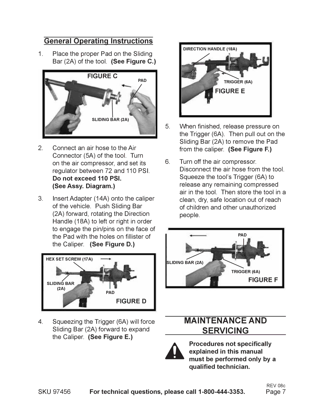
1.Place the proper Pad on the Sliding Bar (2A) of the tool. (See Figure C.)
FIGURE C
PAD
SLIDING BAR (2A)
2.Connect an air hose to the Air Connector (5A) of the tool. Turn on the air compressor, and set its regulator between 72 and 110 PSI.
Do not exceed 110 PSI. (See Assy. Diagram.)
3.Insert Adapter (14A) onto the caliper of the vehicle. Push Sliding Bar
(2A) forward, rotating the Direction Handle (18A) to left or right in order to engage the pin/pins on the face of the Pad with the holes on fillister of the Caliper. (See Figure D.)
Hex Set Screw (17A)
SLIDING BAR (2A)
PAD
FIGURE D
4.Squeezing the Trigger (6A) will force
Sliding Bar (2A) forward to expand the Caliper. (See Figure E.)
DIRECTION HANDLE (18A)
TRIGGER (6A)
FIGURE E
5.When finished, release pressure on the Trigger (6A). Then pull out on the Sliding Bar (2A) to remove the Pad from the caliper. (See Figure F.)
6.Turn off the air compressor. Disconnect the air hose from the tool.
Squeeze the tool’s Trigger (6A) to release any remaining compressed air in the tool. Then store the tool in a clean, dry, safe location out of reach of children and other unauthorized people.
PAD
SLIDING BAR (2A)
TRIGGER (6A)
FIGURE F
Maintenance And
Servicing
Procedures not specifically explained in this manual must be performed only by a qualified technician.
REV 08c
SKU 97456 | For technical questions, please call | Page 7 |
