to Section TOC
to Master TOC
TROUBLESHOOTING & REPAIR
TRIGGER CIRCUIT TEST (continued)
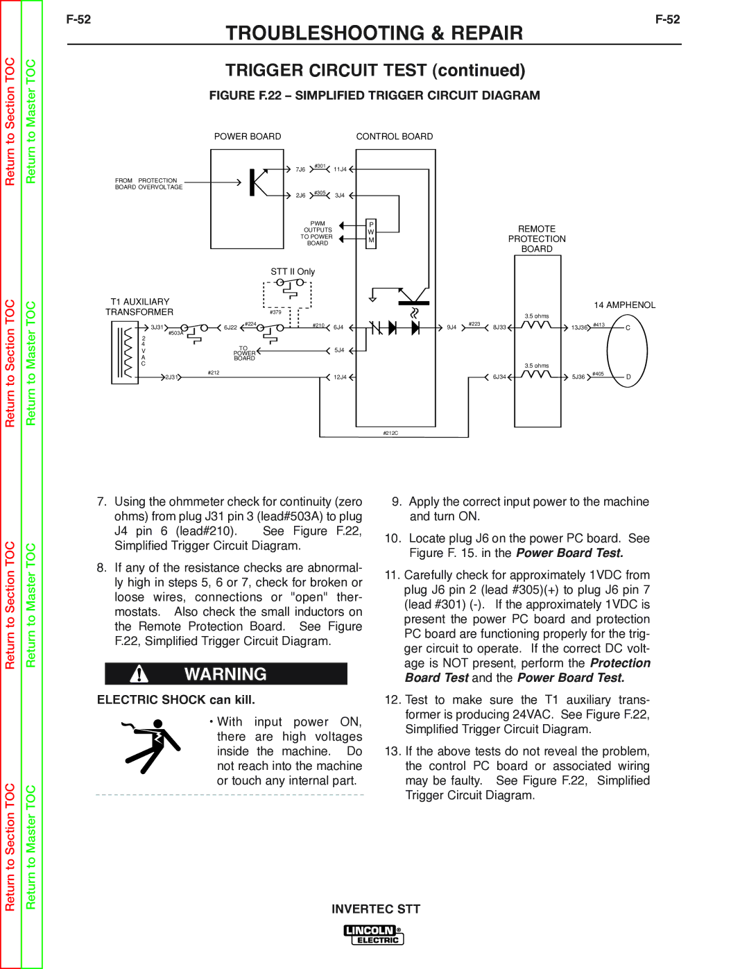
FIGURE F.22 – SIMPLIFIED TRIGGER CIRCUIT DIAGRAM
POWER BOARD | CONTROL BOARD |
Return
Return to Section TOC
Return
Return to Master TOC
|
|
| 7J6 | #301 | 11J4 |
|
|
|
| ||
FROM PROTECTION |
|
|
|
|
|
BOARD OVERVOLTAGE |
|
|
| #305 |
|
|
|
| 2J6 | 3J4 | |
|
|
|
| ||
|
|
|
| PWM | P |
|
|
| OUTPUTS | W | |
|
|
| TO POWER | M | |
|
|
|
| BOARD | |
|
|
|
|
| |
|
|
| STT II Only |
| |
T1 AUXILIARY |
|
|
|
|
|
TRANSFORMER |
|
| #379 |
|
|
3J31 | 6J22 | #224 |
| #210 | 6J4 |
|
| ||||
#503A |
|
|
|
|
|
2 |
|
|
|
|
|
4 |
| TO |
|
| 5J4 |
V |
|
|
| ||
POWER |
|
| |||
A | BOARD |
|
|
| |
C |
|
|
|
|
|
2J31 | #212 |
|
|
| 12J4 |
|
|
|
| ||
#212C
REMOTE
PROTECTION
BOARD
|
|
|
| 14 AMPHENOL | |
|
|
| 3.5 ohms |
|
|
9J4 | #223 | 8J33 | 13J36 | #413 | C |
|
| ||||
|
|
| 3.5 ohms |
|
|
|
| 6J34 | 5J36 | #405 | D |
|
|
| |||
Return to Section TOC
Return to Section TOC
Return to Master TOC
Return to Master TOC
7.Using the ohmmeter check for continuity (zero ohms) from plug J31 pin 3 (lead#503A) to plug J4 pin 6 (lead#210). See Figure F.22, Simplified Trigger Circuit Diagram.
8.If any of the resistance checks are abnormal- ly high in steps 5, 6 or 7, check for broken or loose wires, connections or "open" ther- mostats. Also check the small inductors on the Remote Protection Board. See Figure F.22, Simplified Trigger Circuit Diagram.
WARNING
ELECTRIC SHOCK can kill.
• With input power ON, there are high voltages inside the machine. Do not reach into the machine or touch any internal part.
9.Apply the correct input power to the machine and turn ON.
10.Locate plug J6 on the power PC board. See Figure F. 15. in the Power Board Test.
11.Carefully check for approximately 1VDC from plug J6 pin 2 (lead #305)(+) to plug J6 pin 7 (lead #301)
12.Test to make sure the T1 auxiliary trans- former is producing 24VAC. See Figure F.22, Simplified Trigger Circuit Diagram.
13.If the above tests do not reveal the problem, the control PC board or associated wiring may be faulty. See Figure F.22, Simplified Trigger Circuit Diagram.