Return to Master TOC
Return to Master TOC
TOC
|
|
|
|
|
|
|
|
|
| ELECTRICAL DIAGRAMS |
|
| ||||
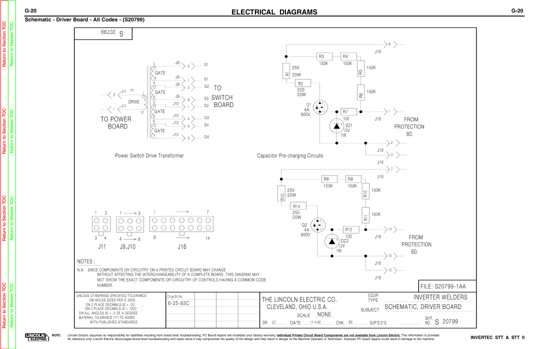
Schematic - Driver Board - All Codes - (S20799) |
|
|
|
|
|
|
|
|
|
|
| |||||
9 | 9 | 7 | 02 | S |
|
|
|
|
|
|
|
|
|
|
|
|
|
|
|
|
|
|
|
|
|
|
|
|
|
|
|
| |
|
|
|
|
|
|
|
|
|
|
|
|
|
|
|
| 8 |
|
|
|
|
|
|
|
|
|
|
|
|
| R3 | R4 | J16 |
|
|
|
|
|
|
|
|
|
|
|
|
|
|
|
| ||
|
|
|
|
|
| 3 |
| J9 | 4 | G1 |
|
| 150K | 150K |
|
|
|
|
|
|
|
|
|
|
|
|
|
| 250 | R5 | 150K |
| |
|
|
|
|
|
|
| GATE | J9 |
|
|
| 1R | 20W |
|
| |
|
|
|
|
|
| 10 |
| S1 |
|
|
|
|
| |||
|
|
|
|
|
| 1 |
|
|
|
|
|
| ||||
|
|
|
|
|
|
|
|
|
|
|
|
| ||||
|
|
|
|
|
| 4 |
| J9 |
|
|
| R2 |
|
|
| |
|
|
|
|
|
|
| 3 | G2 | TO |
|
|
|
| |||
|
|
|
| J11 T1 |
|
|
|
|
| 250 |
|
|
| |||
|
|
|
|
|
| GATE |
|
|
|
| 150K |
| ||||
|
|
|
|
|
|
|
|
|
|
|
|
| ||||
|
|
| 3 | 1 |
| J9 |
|
| SWITCH |
| 20W | R6 |
| |||
|
|
| DRIVE |
| 9 |
| 6 | S2 |
|
|
| |||||
|
|
|
|
| 5 |
|
|
|
|
|
|
| ||||
|
|
|
|
|
| J10 | 1 | S3 | BOARD |
| Q1 |
|
|
| ||
|
|
|
| J11 |
|
|
|
|
|
|
| |||||
|
|
|
|
|
|
|
|
|
|
|
|
|
|
|
| |
|
|
| 1 |
| 12 | GATE |
|
|
|
|
| 4A | R7 |
| 1 | |
|
|
|
|
| J10 |
|
|
|
| 900V |
| |||||
TO POWER |
| 8 |
| 4 | G3 |
|
| 100 | J16 | FROM | ||||||
|
|
|
|
|
| |||||||||||
| 6 |
| J10 | S4 |
|
|
| |||||||||
|
| BOARD |
|
|
| 6 |
|
|
| DZ1 |
| PROTECTION | ||||
|
|
|
|
|
|
|
|
|
| |||||||
|
|
| GATE |
|
|
|
|
|
| |||||||
|
|
|
|
|
| J10 |
|
|
|
|
| 12V |
| BD. | ||
|
|
|
|
|
| 7 |
| 3 | G4 |
|
|
| 1W |
| ||
|
|
|
|
|
|
|
|
|
|
|
|
|
|
| ||
|
|
|
|
|
|
|
|
|
|
|
|
|
|
|
| |
|
|
|
|
|
|
|
|
|
|
|
|
|
|
|
| 2 |
|
|
|
| Power Switch Drive Transformer |
|
| Capacitor |
| J16 | 3 | ||||||
|
|
|
|
|
|
|
| |||||||||
|
|
|
|
|
|
|
|
|
|
|
|
|
|
| J16 |
|
|
|
|
|
|
|
|
|
|
|
|
|
|
|
|
| 7 |
|
|
|
|
|
|
|
|
|
|
|
|
| R8 | R9 | J16 |
|
|
|
|
|
|
|
|
|
|
|
|
|
|
|
| ||
|
|
|
|
|
|
|
|
|
|
|
|
| 150K | 150K |
|
|
|
|
|
|
|
|
|
|
|
|
|
| 250 | 0 | 150K |
| |
|
|
|
|
|
|
|
|
|
|
| 31 | 20W | R1 |
|
| |
|
|
|
|
|
|
|
|
|
|
| R |
|
|
|
|
|
Return to Section
TOC
Return to Master
TOC
1 | 2 | 1 | 3 | 1 | 7 |
3 | 4 | 4 | 6 | 8 | 14 |
| J11 | J9,J10 |
|
| J16 |
NOTES :
N.A. SINCE COMPONENTS OR CIRCUITRY ON A PRINTED CIRCUIT BOARD MAY CHANGE
WITHOUT AFFECTING THE INTERCHANGEABILITY OF A COMPLETE BOARD, THIS DIAGRAM MAY NOT SHOW THE EXACT COMPONENTS OR CIRCUITRY OF CONTROLS HAVING A COMMON CODE NUMBER.
R14
250
20W
Q2
4A
900V
R11
R12
100
![]()
![]() DZ2 12V
DZ2 12V
1W
150K
![]() 14
14
J16
![]() 13
13
J16
![]() 12
12
J16
FROM
PROTECTION
BD.
FILE:
Return to Section
Return to Master
| UNLESS OTHERWISE SPECIFIED TOLERANCE | Ch'ge.Sht.No. | THE LINCOLN ELECTRIC CO. |
| EQUIP. |
| INVERTER WELDERS | |||||||||||||
| ON HOLES SIZES PER |
|
| TYPE |
|
|
|
|
|
| ||||||||||
|
|
|
|
|
|
| ||||||||||||||
| ON 2 PLACE DECIMALS IS + .O2 |
|
| CLEVELAND, OHIO U.S.A. |
|
|
|
| SCHEMATIC, DRIVER BOARD | |||||||||||
| ON 3 PLACE DECIMALS IS + .OO2 |
|
|
|
|
| SUBJECT | |||||||||||||
|
|
|
| |||||||||||||||||
| ON ALL ANGLES IS + .5 OF A DEGREE |
|
|
| SCALE |
| NONE |
|
|
|
|
|
|
|
| |||||
|
|
|
|
|
|
|
|
|
|
|
|
|
|
| ||||||
|
|
|
|
|
|
|
|
|
|
|
|
|
|
| ||||||
| MATERIAL TOLERANCE ("t") TO AGREE |
|
|
|
|
|
|
|
|
|
| SHT. |
|
|
| |||||
|
|
|
|
|
|
|
|
|
|
|
|
|
|
|
|
| ||||
| WITH PUBLISHED STANDARDS |
| DR. | LC | DATE |
| CHK. | BS |
| SUP'S'D'G. |
| NO. S | 20799 |
|
| |||||
|
|
|
|
| ||||||||||||||||
|
|
|
|
|
|
|
|
|
|
|
|
|
|
|
|
|
|
|
|
|
NOTE: Lincoln Electric assumes no responsibility for liablilities resulting from board level troubleshooting. PC Board repairs will invalidate your factory warranty. Individual Printed Circuit Board Components are not available from Lincoln Electric. This information is provided | INVERTEC STT & STT II | |||||||||||||||||||
for reference only. Lincoln Electric discourages board level troubleshooting and repair since it may compromise the quality of the design and may result in danger to the Machine Operator or Technician. Improper PC board repairs could result in damage to the machine. | ||||||||||||||||||||