Return to Section TOC
Return to Section TOC
Return to Master TOC
Return to Master TOC
TROUBLESHOOTING & REPAIR
OUTPUT RECTIFIER REMOVAL AND REPLACEMENT (continued)
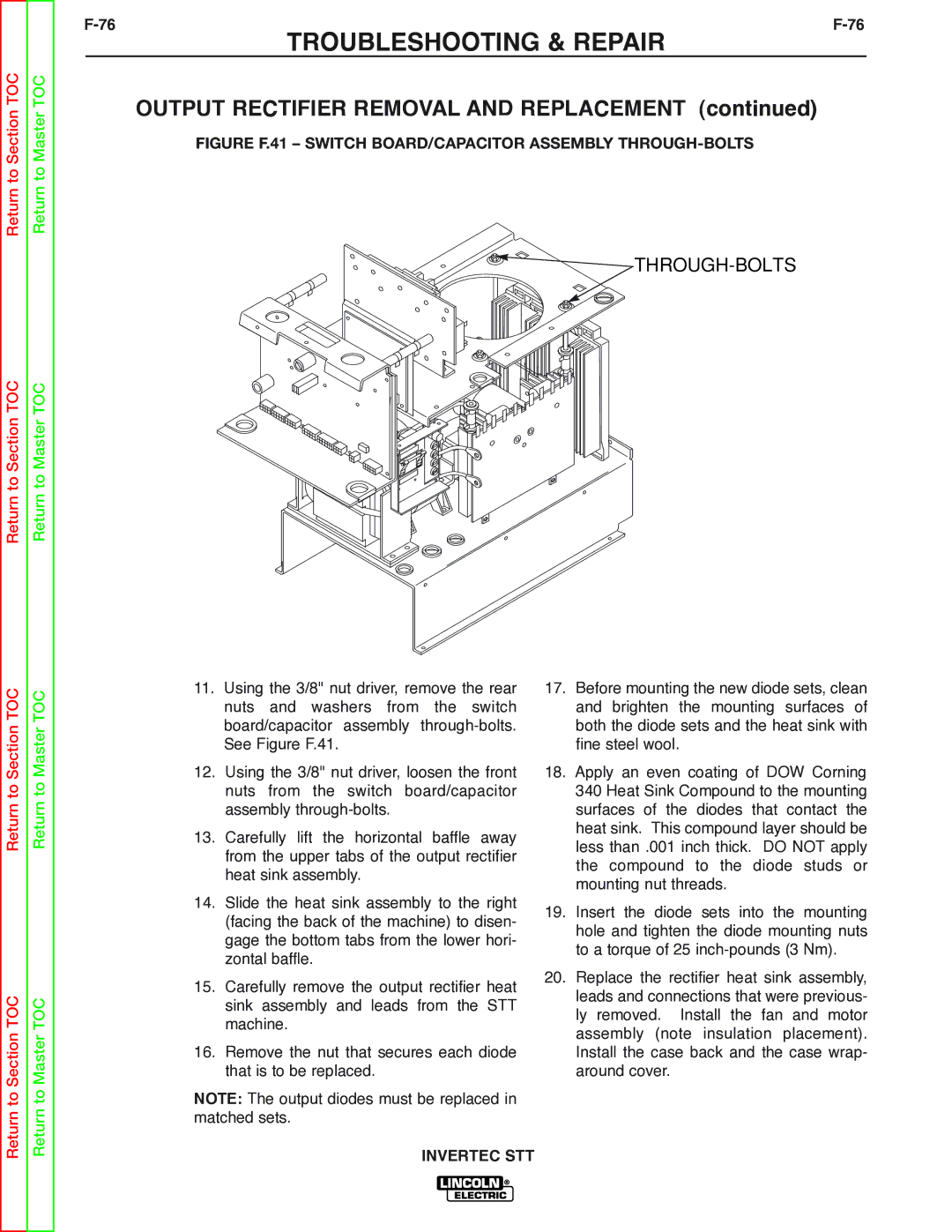
FIGURE F.41 – SWITCH BOARD/CAPACITOR ASSEMBLY THROUGH-BOLTS


 THROUGH-BOLTS
Return to Section TOC
Return to Section TOC
Return to Master TOC
Return to Master TOC
11.Using the 3/8" nut driver, remove the rear nuts and washers from the switch board/capacitor assembly
12.Using the 3/8" nut driver, loosen the front nuts from the switch board/capacitor assembly
13.Carefully lift the horizontal baffle away from the upper tabs of the output rectifier heat sink assembly.
14.Slide the heat sink assembly to the right (facing the back of the machine) to disen- gage the bottom tabs from the lower hori- zontal baffle.
15.Carefully remove the output rectifier heat sink assembly and leads from the STT machine.
16.Remove the nut that secures each diode that is to be replaced.
NOTE: The output diodes must be replaced in matched sets.
17.Before mounting the new diode sets, clean and brighten the mounting surfaces of both the diode sets and the heat sink with fine steel wool.
18.Apply an even coating of DOW Corning 340 Heat Sink Compound to the mounting surfaces of the diodes that contact the heat sink. This compound layer should be less than .001 inch thick. DO NOT apply the compound to the diode studs or mounting nut threads.
19.Insert the diode sets into the mounting hole and tighten the diode mounting nuts to a torque of 25
20.Replace the rectifier heat sink assembly, leads and connections that were previous- ly removed. Install the fan and motor assembly (note insulation placement). Install the case back and the case wrap- around cover.