Return to Section
Return to Section TOC
Return to Master
Return to Master TOC
TEST AFTER REPAIR OF SWITCH BOARDS AND/OR CAPACITORS
The following test must be performed after the switch boards and/or the capacitors have been replaced.
NOTE: Always make sure that switch boards are changed in matched pairs. Never mix an old style (different part number) switch board with a new style (new part number).
TEST PROCEDURE
1.Turn main power OFF.
2.Perform Input Filter Capacitor Discharge Procedure. See the Maintenance section.
WARNING
ELECTRIC SHOCK can kill.
• Before continuing with the test procedure, perform the capacitor discharge procedure to avoid electric shock.
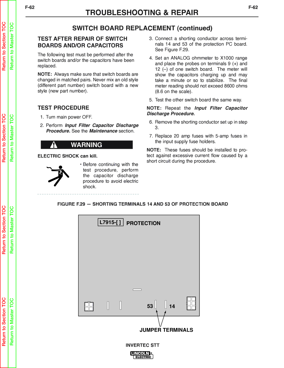
3.Connect a shorting conductor across termi- nals 14 and 53 of the protection PC board. See Figure F.29.
4.Set an ANALOG ohmmeter to X1000 range and place the probes on terminals 9 (+) and 12
5.Test the other switch board the same way.
NOTE: Repeat the Input Filter Capacitor
Discharge Procedure.
6.Remove the shorting conductor set up in step 3.
7.Replace 20 amp fuses with
NOTE: These fuses should be installed to pro- tect against excessive current flow caused by a short circuit during the procedure.
Return to Section TOC
Return to Section TOC
Return to Master TOC
Return to Master TOC
FIGURE F.29 — SHORTING TERMINALS 14 AND 53 OF PROTECTION BOARD
53 |
|
|
| 14 |
JUMPER TERMINALS