Return to Section TOC
Return to Section TOC
Return to Master TOC
Return to Master TOC
TROUBLESHOOTING & REPAIR
CAPACITOR REMOVAL AND REPLACEMENT PROCEDURE (continued)
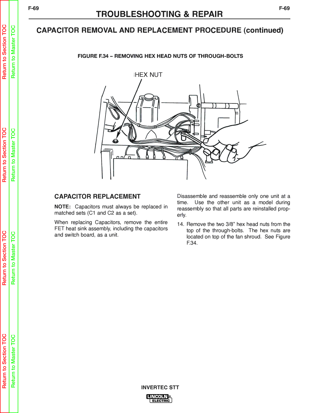
FIGURE F.34 – REMOVING HEX HEAD NUTS OF THROUGH-BOLTS
HEX NUT
Return to Section TOC
Return to Master TOC
CAPACITOR REPLACEMENT
NOTE: Capacitors must always be replaced in matched sets (C1 and C2 as a set).
When replacing Capacitors, remove the entire FET heat sink assembly, including the capacitors and switch board, as a unit.
Disassemble and reassemble only one unit at a time. Use the other unit as a model during reassembly so that all parts are reinstalled prop- erly.
14.Remove the two 3/8” hex head nuts from the top of the
Return to Section TOC
Return to Master TOC