Return to Section TOC
Return to Section TOC
Return to Master TOC
Return to Master TOC
TROUBLESHOOTING & REPAIR
CAPACITOR BALANCE TEST (continued)
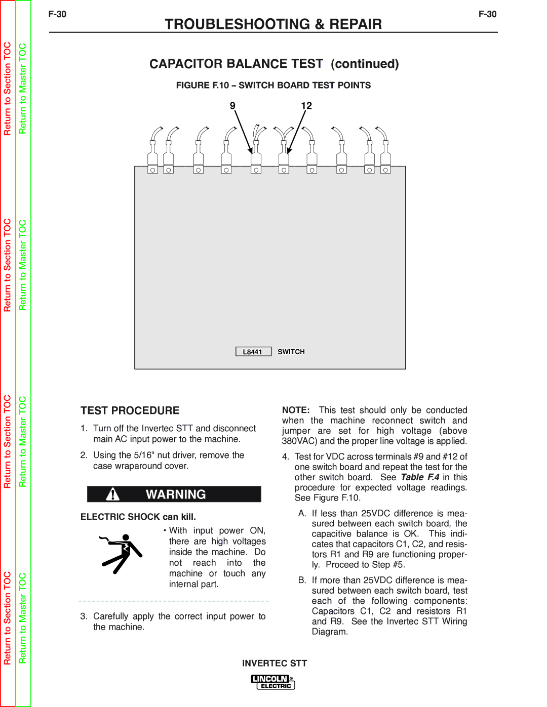
FIGURE F.10 – SWITCH BOARD TEST POINTS
912
|
|
|
|
|
|
|
|
|
|
|
|
|
|
|
|
|
|
|
|
|
|
|
|
|
|
|
|
|
|
|
|
|
|
| SWITCH | ||||||||||
|
|
|
|
|
|
|
|
| L8441 | |||||||||||||
|
|
|
|
|
|
|
|
|
|
|
|
|
|
|
|
|
|
|
|
|
|
|
Return to Section TOC
Return to Section TOC
Return to Master TOC
Return to Master TOC
TEST PROCEDURE
1.Turn off the Invertec STT and disconnect main AC input power to the machine.
2.Using the 5/16" nut driver, remove the case wraparound cover.
WARNING
ELECTRIC SHOCK can kill.
• With input power ON, there are high voltages inside the machine. Do not reach into the machine or touch any internal part.
3.Carefully apply the correct input power to the machine.
NOTE: This test should only be conducted when the machine reconnect switch and jumper are set for high voltage (above 380VAC) and the proper line voltage is applied.
4.Test for VDC across terminals #9 and #12 of one switch board and repeat the test for the other switch board. See Table F.4 in this procedure for expected voltage readings. See Figure F.10.
A.If less than 25VDC difference is mea- sured between each switch board, the capacitive balance is OK. This indi- cates that capacitors C1, C2, and resis- tors R1 and R9 are functioning proper- ly. Proceed to Step #5.
B.If more than 25VDC difference is mea- sured between each switch board, test each of the following components: Capacitors C1, C2 and resistors R1 and R9. See the Invertec STT Wiring Diagram.