Return to Section TOC
Return to Section TOC
Return to Master TOC
Return to Master TOC
TROUBLESHOOTING & REPAIR
TRIGGER CIRCUIT TEST (continued)
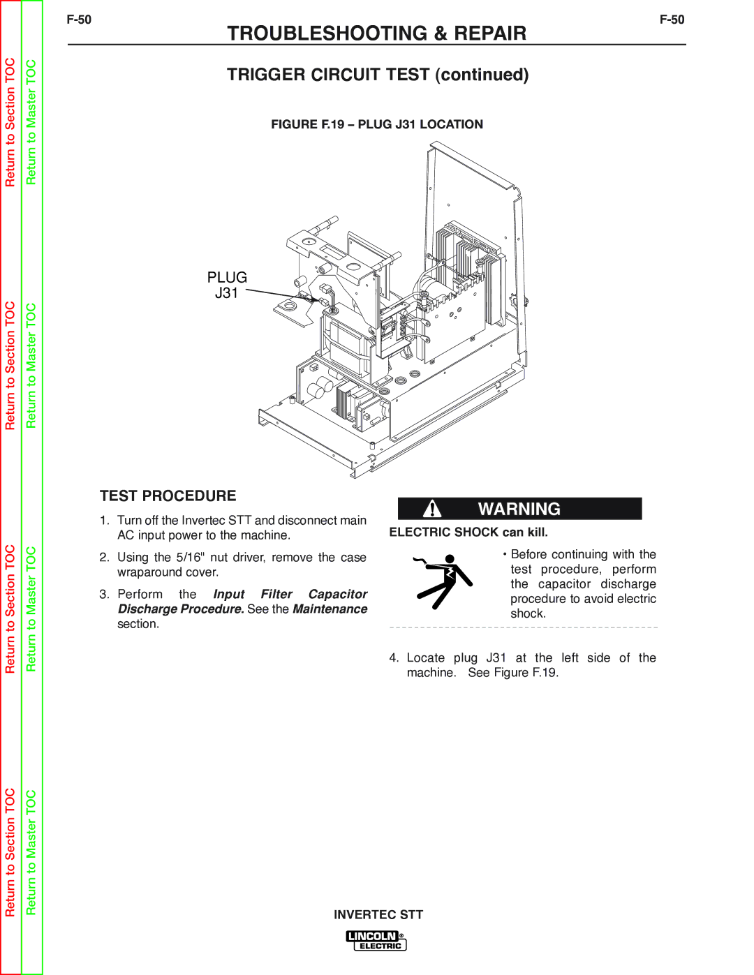
FIGURE F.19 – PLUG J31 LOCATION
PLUG
J31 ![]()
![]()
Return to Section TOC
Return to Master TOC
TEST PROCEDURE
1.Turn off the Invertec STT and disconnect main AC input power to the machine.
2.Using the 5/16" nut driver, remove the case wraparound cover.
3.Perform the Input Filter Capacitor Discharge Procedure. See the Maintenance section.
WARNING
ELECTRIC SHOCK can kill.
•Before continuing with the test procedure, perform the capacitor discharge procedure to avoid electric shock.
4.Locate plug J31 at the left side of the machine. See Figure F.19.
Return to Section TOC
Return to Master TOC