Return to Section TOC
Return to Section TOC
Return to Section TOC
Return to Section TOC
Return to Master TOC
Return to Master TOC
Return to Master TOC
Return to Master TOC
TROUBLESHOOTING & REPAIR
T4 AUXILIARY TRANSFORMER TEST (continued)
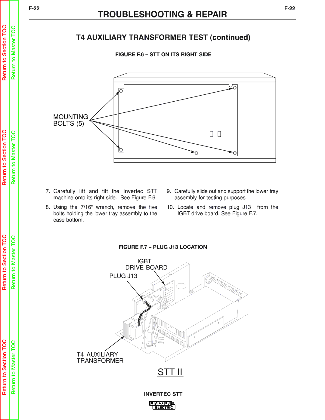
FIGURE F.6 – STT ON ITS RIGHT SIDE
MOUNTING
BOLTS (5)
7. | Carefully lift and tilt the Invertec STT | 9. Carefully slide out and support the lower tray |
| machine onto its right side. See Figure F.6. | assembly for testing purposes. |
8. | Using the 7/16" wrench, remove the five | 10. Locate and remove plug J13 from the |
| bolts holding the lower tray assembly to the | IGBT drive board. See Figure F.7. |
| case bottom. |
|
FIGURE F.7 – PLUG J13 LOCATION
IGBT
DRIVE BOARD
PLUG J13
T4 AUXILIARY
TRANSFORMER
