Return to Section TOC
Return to Master TOC
TROUBLESHOOTING & REPAIR
CAPACITOR REMOVAL AND REPLACEMENT PROCEDURE (continued)
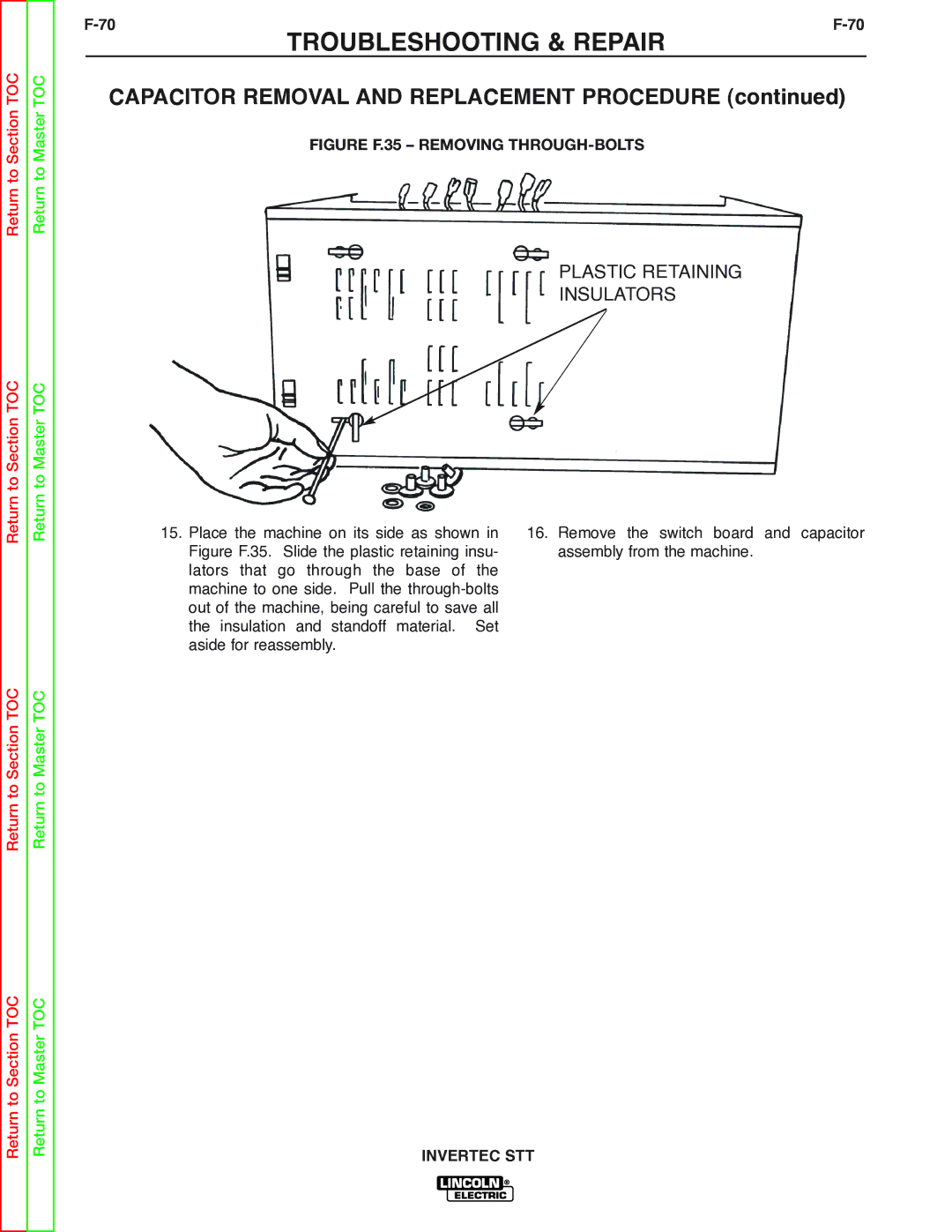
FIGURE F.35 – REMOVING THROUGH-BOLTS
PLASTIC RETAINING
INSULATORS
Return to Section TOC
Return to Section TOC
Return to Master TOC
Return to Master TOC
15.Place the machine on its side as shown in Figure F.35. Slide the plastic retaining insu- lators that go through the base of the machine to one side. Pull the
16.Remove the switch board and capacitor assembly from the machine.
Return to Section TOC
Return to Master TOC