to Section TOC
to Master TOC
TROUBLESHOOTING & REPAIR
POWER BOARD TEST (continued)
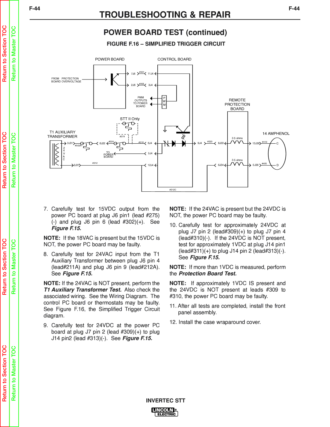
FIGURE F.16 – SIMPLIFIED TRIGGER CIRCUIT
POWER BOARD | CONTROL BOARD |
Return
Return to Section TOC
Return
Return to Master TOC
|
| 7J6 | #301 | 11J4 |
|
|
| ||
FROM PROTECTION |
|
|
|
|
BOARD OVERVOLTAGE |
|
| #305 |
|
|
| 2J6 | 3J4 | |
|
|
| ||
|
|
| PWM | P |
|
| OUTPUTS | W | |
|
| TO POWER | M | |
|
|
| BOARD | |
|
|
|
| |
|
| STT II Only |
| |
T1 AUXILIARY |
|
|
|
|
TRANSFORMER |
| #379 |
|
|
3J31 | #224 |
| #210 | 6J4 |
6J22 |
| |||
|
| |||
#503A |
|
|
|
|
2 |
|
|
|
|
4 | TO |
|
| 5J4 |
V |
|
| ||
POWER |
|
| ||
A | BOARD |
|
|
|
C |
|
|
|
|
2J31 | #212 |
|
| 12J4 |
|
|
| ||
#212C
REMOTE
PROTECTION
BOARD
14 AMPHENOL
|
|
| 3.5 ohms |
|
|
9J4 | #223 | 8J33 | 13J36 #413 | C | |
|
|
| 3.5 ohms |
|
|
|
| 6J34 | 5J36 | #405 | D |
|
|
| |||
Return to Section TOC
Return to Master TOC
7.Carefully test for 15VDC output from the power PC board at plug J6 pin1 (lead #275)
Figure F.15.
NOTE: If the 18VAC is present but the 15VDC is NOT, the power PC board may be faulty.
8.Carefully test for 24VAC input from the T1 Auxiliary Transformer between plug J6 pin 4 (lead#211A) and plug J6 pin 9 (lead#212A). See Figure F.15.
NOTE: If the 24VAC is NOT present, perform the T1 Auxiliary Transformer Test. Also check the associated wiring. See the Wiring Diagram. The control PC board or thermostats may be faulty. See Figure F.16, the Simplified Trigger Circuit diagram.
9.Carefully test for 24VDC at the power PC board at plug J7 pin 2 (lead #309)(+) to plug J14 pin2 (lead
NOTE: If the 24VAC is present but the 24VDC is NOT, the power PC board may be faulty.
10.Carefully test for approximately 24VDC at plug J7 pin 2 (lead#309)(+) to plug J7 pin 4
NOTE: If more than 1VDC is measured, perform the Protection Board Test.
NOTE: If approximately 1VDC IS present and the 24VDC is NOT present at leads #309 to #310, the power PC board may be faulty.
11.After all tests are completed, install the front panel assembly.
12.Install the case wraparound cover.
Return to Section TOC
Return to Master TOC