Return to Section TOC
Return to Section TOC
Return to Master TOC
Return to Master TOC
TROUBLESHOOTING & REPAIR
T1 AUXILIARY TRANSFORMER TEST (continued)
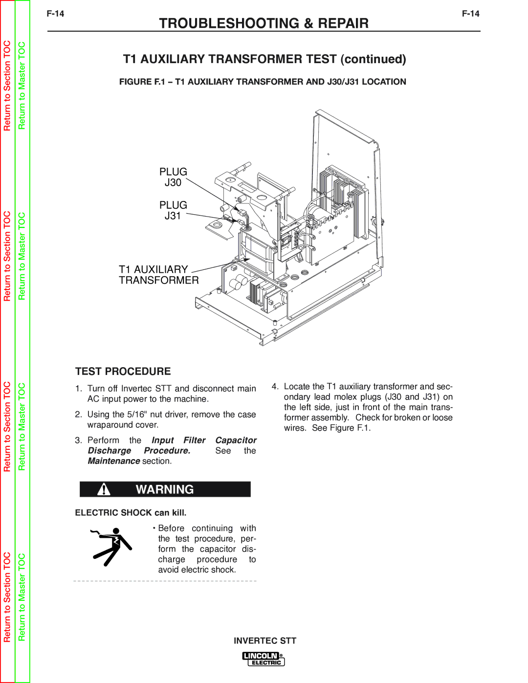
FIGURE F.1 – T1 AUXILIARY TRANSFORMER AND J30/J31 LOCATION
PLUG
J30
PLUG
J31 ![]()
![]()
T1 AUXILIARY ![]()
TRANSFORMER
Return to Section TOC
Return to Master TOC
TEST PROCEDURE
1.Turn off Invertec STT and disconnect main AC input power to the machine.
2.Using the 5/16" nut driver, remove the case wraparound cover.
3.Perform the Input Filter Capacitor
Discharge Procedure. See the Maintenance section.
4.Locate the T1 auxiliary transformer and sec- ondary lead molex plugs (J30 and J31) on the left side, just in front of the main trans- former assembly. Check for broken or loose wires. See Figure F.1.
Return to Section TOC
Return to Master TOC
WARNING
ELECTRIC SHOCK can kill.
• Before continuing with the test procedure, per- form the capacitor dis- charge procedure to avoid electric shock.