Return to Section TOC
Return to Section TOC
Return to Master TOC
Return to Master TOC
TROUBLESHOOTING & REPAIR
INPUT RECTIFIER TEST (continued)
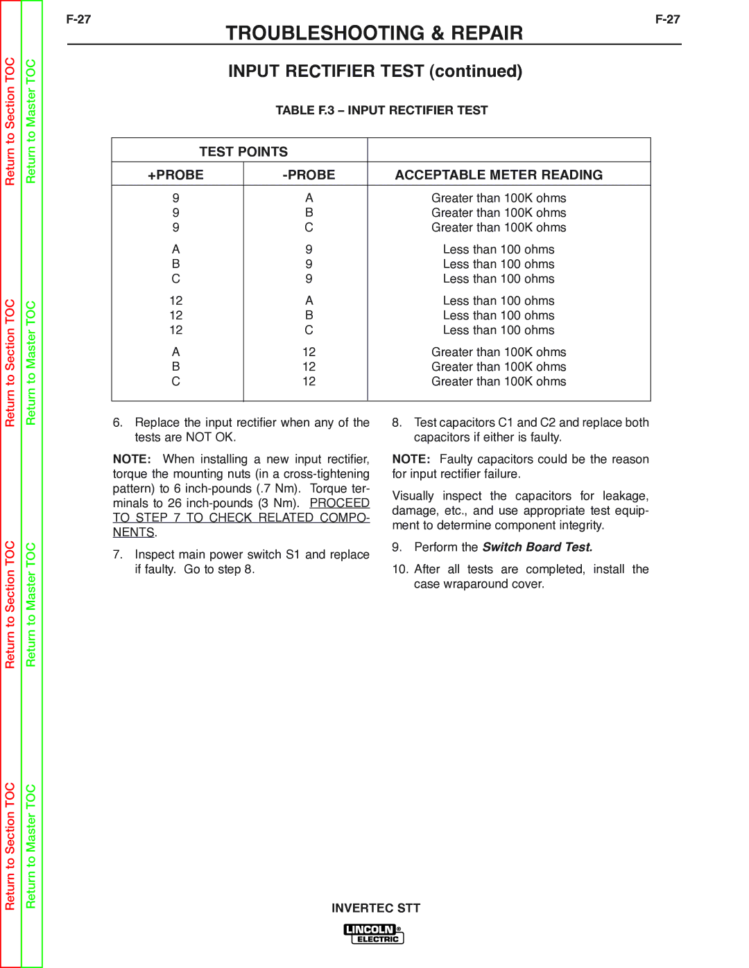
TABLE F.3 – INPUT RECTIFIER TEST
TEST POINTS |
| |
|
|
|
+PROBE |
| ACCEPTABLE METER READING |
|
|
|
9 | A | Greater than 100K ohms |
9 | B | Greater than 100K ohms |
9 | C | Greater than 100K ohms |
A | 9 | Less than 100 ohms |
B | 9 | Less than 100 ohms |
C | 9 | Less than 100 ohms |
12 | A | Less than 100 ohms |
12 | B | Less than 100 ohms |
12 | C | Less than 100 ohms |
A | 12 | Greater than 100K ohms |
B | 12 | Greater than 100K ohms |
C | 12 | Greater than 100K ohms |
|
|
|
Return to Section TOC
Return to Master TOC
6.Replace the input rectifier when any of the tests are NOT OK.
NOTE: When installing a new input rectifier, torque the mounting nuts (in a
7.Inspect main power switch S1 and replace if faulty. Go to step 8.
8.Test capacitors C1 and C2 and replace both capacitors if either is faulty.
NOTE: Faulty capacitors could be the reason for input rectifier failure.
Visually inspect the capacitors for leakage, damage, etc., and use appropriate test equip- ment to determine component integrity.
9.Perform the Switch Board Test.
10.After all tests are completed, install the case wraparound cover.
Return to Section TOC
Return to Master TOC