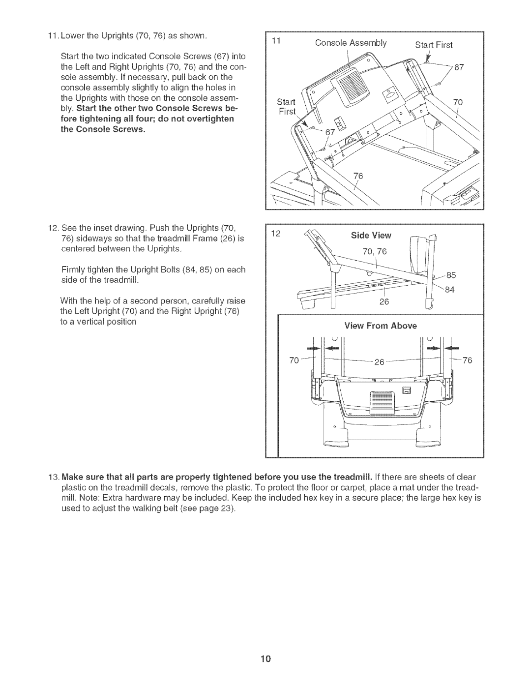
11,LowertheUprights(70,76)asshown, | 11 | ConsoleAssembly | StartFirst |
| |||
StartthetwoindicatedConsoleScrews(67)into |
|
|
|
theLeftandRightUprights(70,76)andthecon- |
|
|
|
sob assembly,if necessary,pullbackonthe |
|
|
|
consoleassemblyslightlytoalignthehobsin |
|
|
|
theUprightswiththoseontheconsoleassem- | Start |
| 7O |
bly,Starttheothertwo ConsoJeScrewsbe_ | First |
|
|
foretighteningaHfour; do notovertighten |
|
|
|
theConsoleScrews. |
|
|
|
76
12,Seetheinsetdrawing,PushtheUprights(70, | 12 | SideView | |
76)sidewayssothatthetreadmillFrame(26)is | |||
|
| ||
centeredbetweentheUprights, |
| 70,76 |
FirmlytightentheUprightBolts(84,85)on each sideofthetreadmill,
WiththeheUpofa secondperson,carefullyraise theLeftUpright(70)andtheRightUpright(76) toaverticalposition
26
View From Above
m
70 /
13, Make sure that aH parts are properly tightened plastic on the treadmill decals, remove the plastic, mill, Note: Extra hardware may be included, Keep used to adjust the walking belt (see page 23),
before you use the treadmill, if there are sheets of clear To protect the floor or carpet, place a mat under the tread° the included hex key in a secure place; the large hex key is
10
