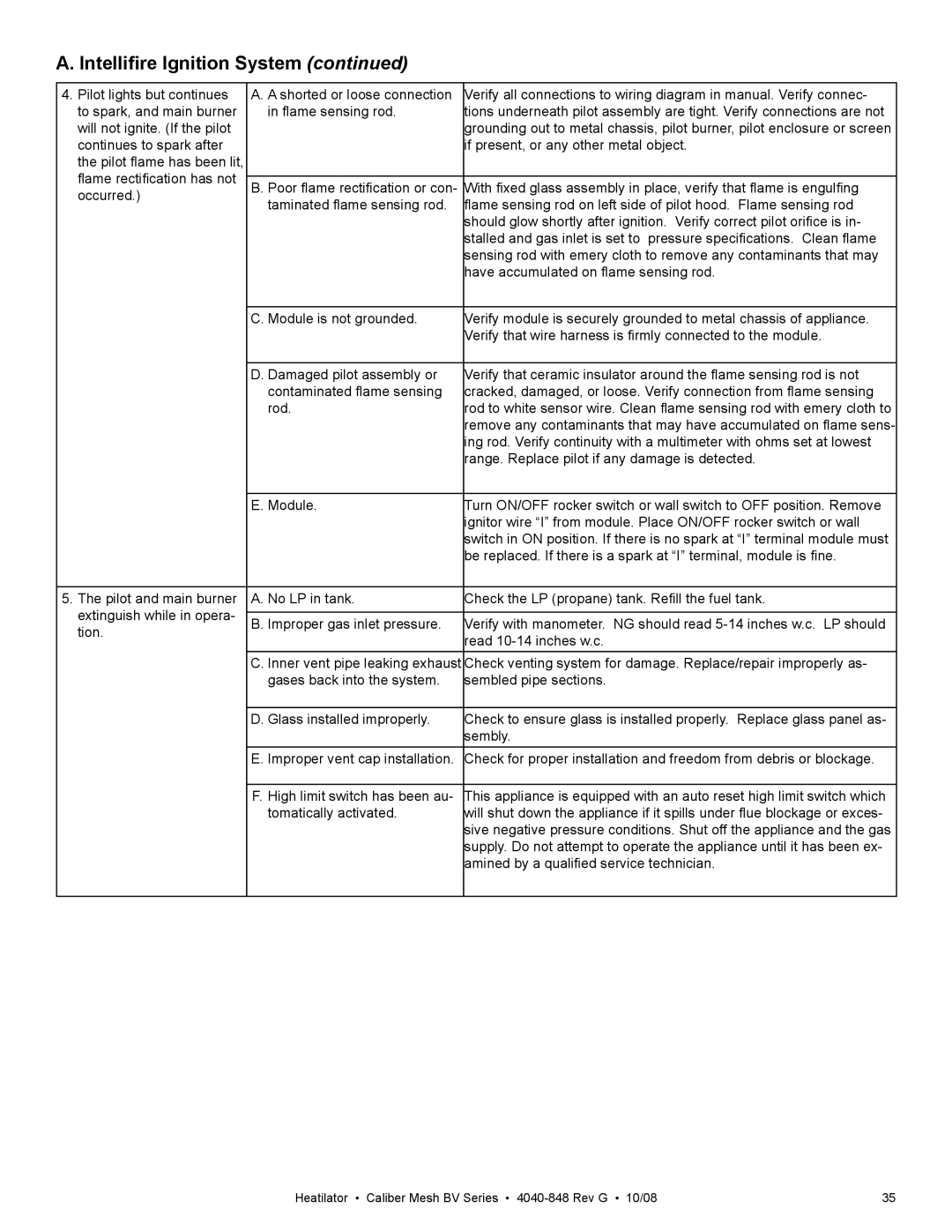
A. Intellifire Ignition System (continued)
4. Pilot lights but continues | A. A shorted or loose connection | Verify all connections to wiring diagram in manual. Verify connec- | |
to spark, and main burner | in flame sensing rod. | tions underneath pilot assembly are tight. Verify connections are not | |
will not ignite. (If the pilot |
| grounding out to metal chassis, pilot burner, pilot enclosure or screen | |
continues to spark after |
| if present, or any other metal object. | |
the pilot flame has been lit, |
|
| |
flame rectification has not |
|
| |
B. Poor flame rectification or con- | With fixed glass assembly in place, verify that flame is engulfing | ||
occurred.) | taminated flame sensing rod. | flame sensing rod on left side of pilot hood. Flame sensing rod | |
| |||
|
| should glow shortly after ignition. Verify correct pilot orifice is in- | |
|
| stalled and gas inlet is set to pressure specifications. Clean flame | |
|
| sensing rod with emery cloth to remove any contaminants that may | |
|
| have accumulated on flame sensing rod. | |
|
|
| |
| C. Module is not grounded. | Verify module is securely grounded to metal chassis of appliance. | |
|
| Verify that wire harness is firmly connected to the module. | |
|
|
| |
| D. Damaged pilot assembly or | Verify that ceramic insulator around the flame sensing rod is not | |
| contaminated flame sensing | cracked, damaged, or loose. Verify connection from flame sensing | |
| rod. | rod to white sensor wire. Clean flame sensing rod with emery cloth to | |
|
| remove any contaminants that may have accumulated on flame sens- | |
|
| ing rod. Verify continuity with a multimeter with ohms set at lowest | |
|
| range. Replace pilot if any damage is detected. | |
|
|
| |
| E. Module. | Turn ON/OFF rocker switch or wall switch to OFF position. Remove | |
|
| ignitor wire “I” from module. Place ON/OFF rocker switch or wall | |
|
| switch in ON position. If there is no spark at “I” terminal module must | |
|
| be replaced. If there is a spark at “I” terminal, module is fine. | |
|
|
| |
5. The pilot and main burner | A. No LP in tank. | Check the LP (propane) tank. Refill the fuel tank. | |
extinguish while in opera- |
|
| |
B. Improper gas inlet pressure. | Verify with manometer. NG should read | ||
tion. | |||
| read | ||
|
| ||
| C. Inner vent pipe leaking exhaust | Check venting system for damage. Replace/repair improperly as- | |
| gases back into the system. | sembled pipe sections. | |
|
|
| |
| D. Glass installed improperly. | Check to ensure glass is installed properly. Replace glass panel as- | |
|
| sembly. | |
| E. Improper vent cap installation. | Check for proper installation and freedom from debris or blockage. | |
|
|
| |
| F. High limit switch has been au- | This appliance is equipped with an auto reset high limit switch which | |
| tomatically activated. | will shut down the appliance if it spills under flue blockage or exces- | |
|
| sive negative pressure conditions. Shut off the appliance and the gas | |
|
| supply. Do not attempt to operate the appliance until it has been ex- | |
|
| amined by a qualified service technician. | |
|
|
|
Heatilator • Caliber Mesh BV Series • | 35 |
