
ESCAPE-42DV specifications
Hearth and Home Technologies has established itself as a leader in the hearth industry, bringing innovation and style to homes across North America. One of their standout offerings is the ESCAPE-42DV, a versatile and efficient direct vent gas fireplace that combines modern design with cutting-edge technology.The ESCAPE-42DV features a sleek, contemporary look that seamlessly integrates into various home aesthetics. With a viewing area of 42 inches, it provides a wide and inviting flame display that enhances the ambiance of any living space. Its generous size makes it an ideal centerpiece for larger rooms, allowing for a captivating focal point in homes with open floor plans.
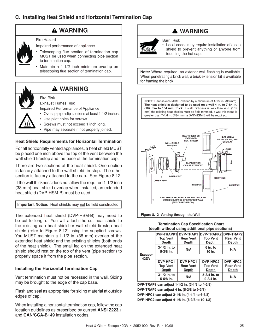
One of the notable characteristics of the ESCAPE-42DV is its direct vent technology, which allows for efficient operation without the need for a traditional chimney. This system ensures that combustion gases are expelled outside while bringing in fresh air for combustion, creating a cleaner and more energy-efficient environment. Homeowners can enjoy the warmth and comfort of real flames without the hassle of maintaining a complex venting system.
Efficiency is key in today's eco-conscious world, and the ESCAPE-42DV exceeds expectations with its impressive energy ratings. It operates at a high efficiency level, providing excellent heating capability while minimizing gas consumption. This not only reduces utility bills but also makes it an environmentally friendly choice, appealing to those who prioritize sustainability.
Hearth and Home Technologies have also incorporated advanced features into the ESCAPE-42DV, including a variety of heat and flame control options. The unit comes equipped with a programmable remote control, allowing users to adjust the flame height and heat output with ease. This personalization ensures comfort whether homeowners are looking for a cozy ambiance or substantial warmth during colder months.
The fireplace can be styled according to individual preferences, thanks to customizable options such as various media choices, including beautiful ceramic logs and glowing embers. The ability to personalize the appearance of the ESCAPE-42DV enhances its appeal, making it a functional yet stylish addition to any home.
With its combination of design elegance, innovative technology, and operational efficiency, the Hearth and Home Technologies ESCAPE-42DV direct vent gas fireplace is an exceptional choice for homeowners seeking to elevate their living spaces. It stands as a testament to the brand's commitment to quality and innovation in the hearth industry, delivering warmth and beauty to modern homes.