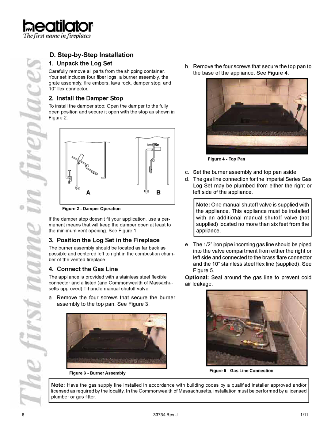
FI36SL, FI36ML, FI42SL, FI36M, FI36S specifications
Hearth and Home Technologies is a leading manufacturer of high-quality fireplaces, and their series of gas inserts, including the FI42S, FI42ML, FI42M, FI36S, and FI36M, exemplify innovation and modern design in home heating solutions. Each model in this lineup brings unique features, advanced technology, and aesthetic appeal, ensuring they meet diverse consumer preferences.Starting with the FI42S model, it is designed to provide a powerful heating solution with its expansive viewing area. The FI42S boasts a sleek and contemporary design that fits seamlessly into any living space. Its efficient gas-burning system optimizes heat output while maintaining lower emissions, making it both an environmentally conscious choice and a cost-effective one in terms of energy consumption.
Transitioning to the FI42ML, this model features a modern linear design, emphasizing style without sacrificing functionality. The FI42ML provides a wide flame viewing area, which enhances the ambiance of any room. With its multi-function remote control, users can effortlessly adjust settings to create the perfect atmosphere at the push of a button, seamlessly merging convenience with luxury.
Next is the FI42M, a model that prioritizes versatility and performance. Equipped with innovative heating technologies, it allows for customizable flame and heat settings, making it a great option for those who desire a personalized experience. Its larger size also means it can accommodate more substantial spaces, providing warmth and comfort for gatherings with family or friends.
The FI36S and FI36M models cater to those looking for efficient heating in slightly smaller dimensions. The FI36S combines traditional styling with modern performance, making it an excellent fit for both classic and contemporary interiors. On the other hand, the FI36M enhances the minimalist aesthetic with its streamlined design and provides outstanding energy efficiency, reducing environmental impact while ensuring optimum warmth.
All models feature Hearth and Home Technologies' proprietary technology and safety features, including advanced venting options, allowing installation flexibility while ensuring safe operation. In summary, the FI42S, FI42ML, FI42M, FI36S, and FI36M represent the pinnacle of fireplace design. With their focus on efficiency, advanced features, and stunning aesthetics, these gas inserts redefine comfort and style in home heating solutions. These models are perfect for homeowners seeking a balance of functionality, aesthetics, and innovation in their fireplaces.

