6000TR-OAK-IPI specifications
The Heat & Glo LifeStyle 6000TR-OAK-IPI is a modern gas fireplace designed to enhance the ambiance of any living space while providing efficiency and convenience. This model stands out for its innovative features and sleek design, making it a popular choice for homeowners looking to combine aesthetics with functionality.One of the main features of the LifeStyle 6000TR-OAK-IPI is its realistic oak log set, which provides a traditional fireplace look without the hassle of wood. The logs are accentuated by a vibrant flame that can be adjusted to suit the user's preferences, ensuring a cozy atmosphere whether for a small gathering or a romantic evening.
The fireplace incorporates advanced technology, notably the Intellifire Ignition System (IPI). This system not only simplifies the ignition process but also enhances safety and energy efficiency. The IPI technology ensures that the fireplace ignites smoothly whenever needed and automatically shuts down when not in use, conserving gas and reducing costs.
Another significant characteristic of the LifeStyle 6000TR is its customizable design. Homeowners can choose from various trim and surround options, allowing the unit to blend seamlessly with different interior styles. The fireplace features a large viewing area, delivering a mesmerizing spectacle of flames that draws the eye and serves as a stunning focal point in any room.
Performance-wise, the LifeStyle 6000TR boasts an impressive heating capacity. With its powerful heat output, it can effectively warm a large area, making it perfect for open-concept living spaces. Furthermore, its efficient combustion system ensures that emissions are minimized, making it an environmentally friendly option.
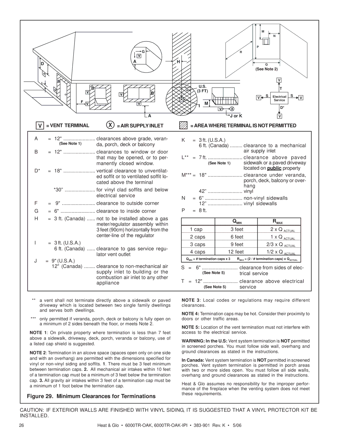
Installation is made easier with the model's flexible venting options, allowing for both direct venting and vent-free configurations. Homeowners can select the installation method that best suits their heating needs and home design.
With a combination of style, efficiency, and modern technology, the Heat & Glo LifeStyle 6000TR-OAK-IPI is an exceptional choice for those looking to elevate their home heating experience. It blends warmth with aesthetic appeal, making it a worthwhile investment for any household.