7 Electrical Information
A. Recommendation for Wire
Note: This appliance must be electrically wired and grounded in accordance with local codes or, in the absence of local codes, with National Electric Code ANSI/NFPA
CSA C22.1.
C. Intellifire Ignition System Wiring
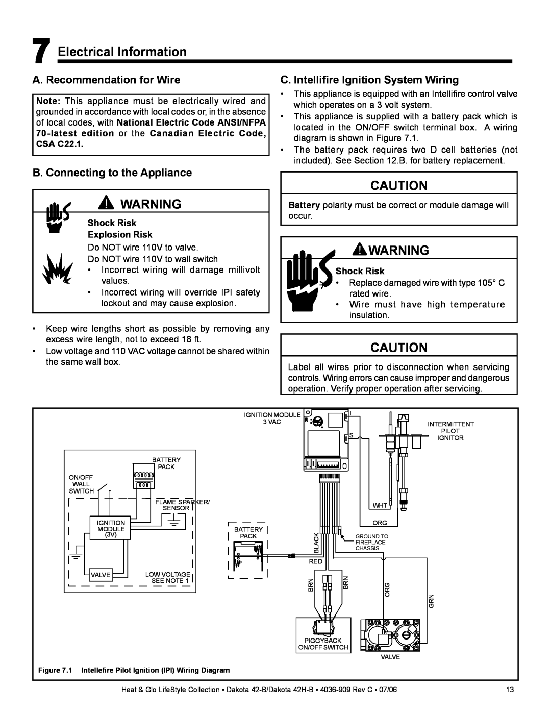
•This appliance is equipped with an Intellifire control valve which operates on a 3 volt system.
•This appliance is supplied with a battery pack which is located in the ON/OFF switch terminal box. A wiring diagram is shown in Figure 7.1.
•The battery pack requires two D cell batteries (not included). See Section 12.B. for battery replacement.
B. Connecting to the Appliance
![]() WARNING
WARNING
Shock Risk
Explosion Risk
Do NOT wire 110V to valve.
Do NOT wire 110V to wall switch
•Incorrect wiring will damage millivolt values.
•Incorrect wiring will override IPI safety lockout and may cause explosion.
•Keep wire lengths short as possible by removing any excess wire length, not to exceed 18 ft.
•Low voltage and 110 VAC voltage cannot be shared within the same wall box.
CAUTION
Battery polarity must be correct or module damage will occur.
![]() WARNING
WARNING
Shock Risk
•Replace damaged wire with type 105° C rated wire.
•Wire must have high temperature insulation.
CAUTION
Label all wires prior to disconnection when servicing controls. Wiring errors can cause improper and dangerous operation. Verify proper operation after servicing.
|
| IGNITION MODULE |
| I |
| |
|
|
| 3 VAC |
|
| INTERMITTENT |
|
|
|
|
| S | PILOT |
|
|
|
|
| IGNITOR | |
|
|
|
|
|
| |
| BATTERY |
|
|
|
|
|
| PACK |
|
|
|
|
|
ON/OFF |
|
|
|
|
|
|
WALL |
|
|
|
|
|
|
SWITCH |
|
|
|
|
|
|
| FLAME SPARKER/ |
|
|
| WHT |
|
| SENSOR |
|
|
|
| |
|
|
|
|
|
| |
IGNITION |
| BATTERY |
|
| ORG |
|
MODULE |
|
|
|
|
| |
(3V) |
| PACK | BLACK |
| GROUND TO |
|
|
|
|
| FIREPLACE |
| |
|
|
|
| CHASSIS |
| |
|
|
|
|
|
| |
|
|
| RED |
|
|
|
VALVE | LOW VOLTAGE |
| BRN | BRN |
|
|
| SEE NOTE 1 |
| ORG |
| ||
|
|
| GRN | |||
|
|
| PIGGYBACK |
|
|
|
|
|
| ON/OFF SWITCH |
|
| |
|
|
|
|
| VALVE |
|
Figure 7.1 Intellefire Pilot Ignition (IPI) Wiring Diagram |
|
|
|
|
| |
Heat & Glo LifeStyle Collection • Dakota | 13 | |||||