
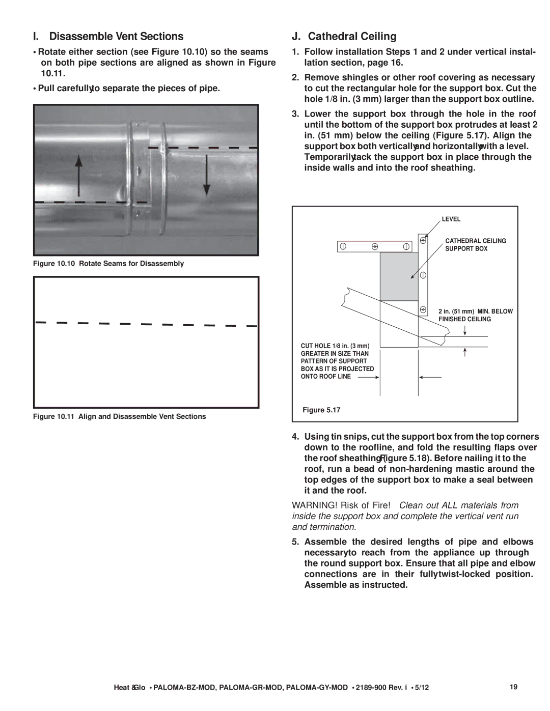
PALOMA-BZ-MOD specifications
The Heat & Glo LifeStyle PALOMA-BZ-MOD is an innovative and stylish gas fireplace designed to elevate the ambiance of any living space. This modern fireplace combines functionality, aesthetics, and advanced technology, making it an ideal choice for homeowners seeking both warmth and sophistication.One of the standout features of the PALOMA-BZ-MOD is its contemporary design. With its clean lines and minimalist profile, this fireplace seamlessly integrates into various interior styles—from ultra-modern to classic decor. The wide viewing area provided by the expansive glass front ensures that the mesmerizing flames are the focal point of any room, creating an inviting and cozy atmosphere.
The PALOMA-BZ-MOD incorporates advanced heating technologies that enhance efficiency and performance. Its powerful heating capacity can warm spaces effectively, allowing for comfortable living even in colder climates. The unit is designed to operate quietly, ensuring that the crackling flames are the only sound you hear. This makes it perfect for homes where relaxation and tranquility are priorities.
Another noteworthy aspect of the PALOMA-BZ-MOD is its customizable features. Homeowners can choose from a variety of decorative media options, including ceramic logs, glass beads, or pebbles, allowing for personalization that complements individual style preferences. The flame presentation is adjustable, giving users control over the height and intensity of the flames, thus enhancing both aesthetics and functionality.
The fireplace is equipped with innovative technologies for ease of use. The flexible installation options mean it can be placed in a variety of locations, whether it's a central feature in a living room or an elegant addition to a dining area. Additionally, a user-friendly remote control allows for convenient operation, enabling users to turn the fireplace on or off and adjust settings from across the room.
Safety is a priority with the PALOMA-BZ-MOD. It features an advanced safety shut-off system, ensuring peace of mind for homeowners. The continuous pilot light and electronic ignition system enhance reliability, providing instant warmth when needed.
In summary, the Heat & Glo LifeStyle PALOMA-BZ-MOD exemplifies a harmonious blend of modern design and advanced technology. With its captivating flames, customizable features, and efficient heating performance, it serves as both a functional heating solution and a stunning piece of decor, making it a popular choice for any contemporary home.