|
|
|
|
|
| a |
|
| j |
| t |
|
|
|
|
| h |
| c | |
|
|
|
|
|
| |
|
| j | j | e | e | d |
|
|
|
|
|
| |
|
| OPENABLE |
| h |
|
|
|
| WINDOW |
|
|
| |
|
|
|
| P |
| |
|
|
|
| h |
| |
| n |
| DOOR |
|
| |
|
|
|
|
| ||
f |
| k |
| t |
| M |
|
|
|
| |||
|
|
|
|
|
| |
| c | I |
|
|
| d |
|
|
|
| b | ||
|
|
|
|
| ||
|
|
|
| g |
|
|
|
| k |
|
|
|
|
SEE NOTE 2
SEE NOTE 3
g
t
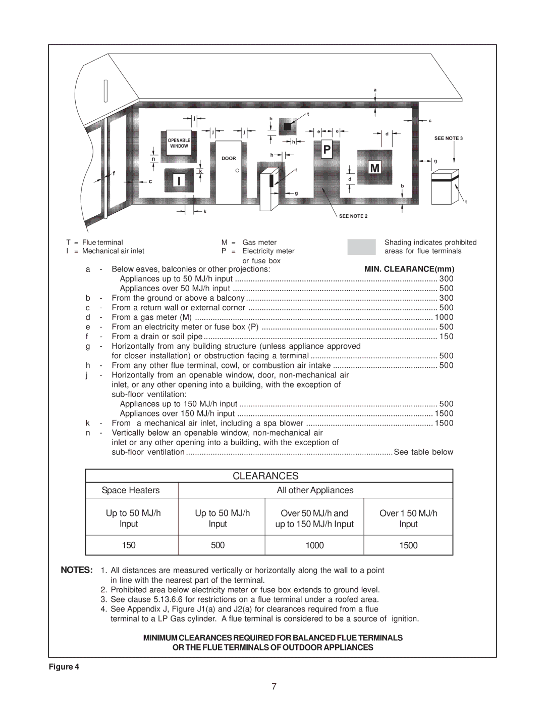
T | = | Flue terminal | M | = | Gas meter |
I | = | Mechanical air inlet | P | = | Electricity meter |
|
|
|
|
| or fuse box |
Shading indicates prohibited areas for flue terminals
a | - Below eaves, balconies or other projections: | MIN. CLEARANCE(mm) |
| Appliances up to 50 MJ/h input | 300 |
| Appliances over 50 MJ/h input | 500 |
b | - From the ground or above a balcony | 300 |
c | - From a return wall or external corner | 500 |
d | - From a gas meter (M) | 1000 |
e | - From an electricity meter or fuse box (P) | 500 |
f | - From a drain or soil pipe | 150 |
g | - Horizontally from any building structure (unless appliance approved |
|
| for closer installation) or obstruction facing a terminal | 500 |
h | - From any other flue terminal, cowl, or combustion air intake | 500 |
j- Horizontally from an openable window, door,
Appliances up to 150 MJ/h input | 500 |
Appliances over 150 MJ/h input | 1500 |
k - From a mechanical air inlet, including a spa blower | 1500 |
n- Vertically below an openable window,
CLEARANCES
Space Heaters |
| All other Appliances |
|
|
|
|
|
Up to 50 MJ/h | Up to 50 MJ/h | Over 50 MJ/h and | Over 1 50 MJ/h |
Input | Input | up to 150 MJ/h Input | Input |
|
|
|
|
150 | 500 | 1000 | 1500 |
|
|
|
|
NOTES: 1. All distances are measured vertically or horizontally along the wall to a point in line with the nearest part of the terminal.
2.Prohibited area below electricity meter or fuse box extends to ground level.
3.See clause 5.13.6.6 for restrictions on a flue terminal under a roofed area.
4.See Appendix J, Figure J1(a) and J2(a) for clearances required from a flue
terminal to a LP Gas cylinder. A flue terminal is considered to be a source of ignition.
MINIMUM CLEARANCES REQUIRED FOR BALANCED FLUE TERMINALS
OR THE FLUE TERMINALS OF OUTDOOR APPLIANCES
Figure 4
7