15 Reference Materials
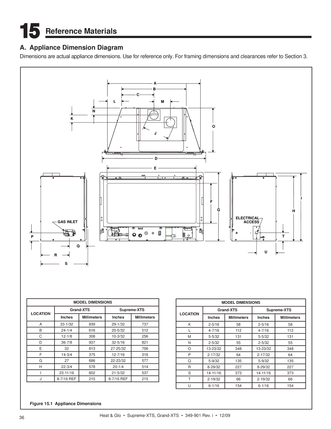
A. Appliance Dimension Diagram
Dimensions are actual appliance dimensions. Use for reference only. For framing dimensions and clearances refer to Section 3.
N
K
L
A
B
C
M
J
O
GAS INLET
P
Q
R
S
![]() D
D
![]() E
E ![]()
I
F
GH
ELECTRICAL
ACCESS
T
U
MODEL DIMENSIONS
LOCATION | |||||
|
|
|
| ||
Inches | Millimeters | Inches | Millimeters | ||
| |||||
|
|
|
|
| |
A | 839 | 737 | |||
B | 616 | 512 | |||
C | 308 | 256 | |||
D | 937 | 821 | |||
E | 32 | 813 | 706 | ||
F | 375 | 316 | |||
G | 27 | 686 | 577 | ||
H | 578 | 514 | |||
I | 602 | 537 | |||
J | 215 | 215 | |||
MODEL DIMENSIONS
LOCATION | |||||
|
|
|
| ||
Inches | Millimeters | Inches | Millimeters | ||
| |||||
|
|
|
|
| |
K | 58 | 58 | |||
L | 112 | 112 | |||
M | 131 | 131 | |||
N | 55 | 55 | |||
O | 348 | 348 | |||
P | 64 | 64 | |||
Q | 135 | 135 | |||
R | 227 | 227 | |||
S | 373 | 373 | |||
T | 66 | 66 | |||
|
|
|
|
| |
U | 154 | 154 | |||
Figure 15.1 Appliance Dimensions
36 | Heat & Glo • |
|
