XLR-PLUS-N-AU, XLR-PLUS-PB-AU specifications
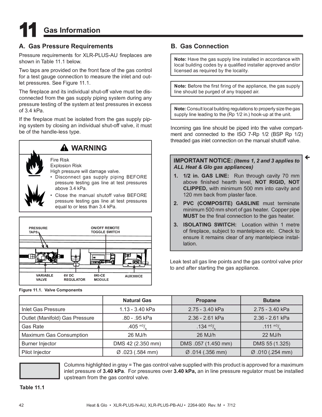
The Heat & Glo LifeStyle XLR-PLUS-PB-AU and XLR-PLUS-N-AU are modern gas fireplaces designed to provide both comfort and aesthetic appeal to your home. These models exemplify innovative design, advanced technology, and user-friendly features that make them ideal for any living space.One of the standout features of the XLR-PLUS series is its elegant linear design, which offers a contemporary aesthetic suitable for various interior styles. The fireplaces are available in multiple sizes, ensuring they can fit into a wide range of spaces, whether in a cozy den or a spacious open-concept living area. The sleek appearance is complemented by a variety of front options, allowing homeowners to customize their fireplace to match personal tastes and home décor.
The heating technology in the XLR-PLUS fireplaces is another key highlight. Equipped with advanced gas burner systems, these units deliver efficient heating performance, making them an excellent choice for year-round use. The adjustable flame height feature not only enhances ambiance but also allows users to customize the heat output based on their needs. This flexibility contributes to energy savings, as users can efficiently manage their heating preferences.
Notably, the XLR-PLUS models incorporate the IntelliFire® Ignition System, a state-of-the-art technology that ensures reliable lighting and easy operation. This system simplifies the ignition process, allowing users to start their fireplace with the push of a button. Furthermore, the fireplaces come with a remote control that provides added convenience, enabling users to adjust settings from the comfort of their seat.
Safety is a top priority with the Heat & Glo LifeStyle series. These fireplaces feature a built-in safety shut-off mechanism that automatically turns off the unit if it detects any issues, offering peace of mind for users. Additionally, the glass front is designed to remain cool to the touch, reducing the risk of burns, making them a family-friendly option.
In terms of installation, both the XLR-PLUS-PB-AU and XLR-PLUS-N-AU models are designed with versatility in mind. They can be installed in various configurations, including built-in, wall-mounted, or as part of a custom cabinetry project. This adaptability allows homeowners to seamlessly integrate the fireplace into their space.
In summary, the Heat & Glo LifeStyle XLR-PLUS-PB-AU and XLR-PLUS-N-AU fireplaces combine cutting-edge technology, customizable design, and reliable performance. With features that prioritize both safety and user experience, these models are perfect for those looking to enhance their living spaces with warmth and style.

