Submittal Data

HBH Series

Heat Controller, Inc.

Selection Procedure

Step 1 Determine the actual heating and cooling loads at the desired dry bulb and wet bulb conditions.

Step 2 Obtain the following design parameters: Entering water temperature, water flow rate in GPM, air flow in CFM, water flow pressure drop and design wet and dry bulb temperatures. Air flow CFM should be between 300 and 450 CFM per ton. Unit water pressure drop should be kept as close as possible to each other to make water balancing easier. Go to the appropriate tables and find the proper indicated water flow and water temperature.

Step 3 Select a unit based on total and sensible cooling conditions. Select a unit which is closest to the actual cooling load.

Step 4 Use data from performance tables at the design water flow and water temperature. Read the total and sensible cooling capacities (Note: interpolation is permissible, extrapolation is not).

Step 5 Read the heating capacity. If it exceeds the design criteria it is acceptable. It is quite normal for Water-Source Heat Pumps to be selected on cooling capacity only since the heating output is usually greater than the cooling capacity.

Step 6 Determine the correction factors associated with the variable factors of dry bulb and wet bulb (page 14).

Corrected Total Cooling =

tabulated total cooling x wet bulb correction. Corrected Sensible Cooling =

tabulated sensible cooling x wet/dry bulb correction.

Step 7 Determine the correction factor associated with antifreeze in system loop. If heating EWT is 50°F or below you may have to use antifreeze. Calculate leaving water temperature per performance data selection notes (page 18). If antifreeze is required, use correction table for correcting total and sensible capacities.

Step 8 Compare the corrected capacities to the load requirements. Normally if the capacities are within 10% of the loads, the equipment is acceptable. It is better to undersize than oversize, as undersizing improves humidity control, reduces sound levels and extends the life of the equipment.

Step 9 When completed, calculate water temperature rise and assess the selection. If the units selected are not within 10% of the load calculations, then review what effect changing the GPM, water temperature and/or air flow and air temperature would have on the corrected capacities. If the desired capacity cannot be achieved, select the next larger or smaller unit and repeat the procedure. Remember, when in doubt, undersize slightly for best performance.

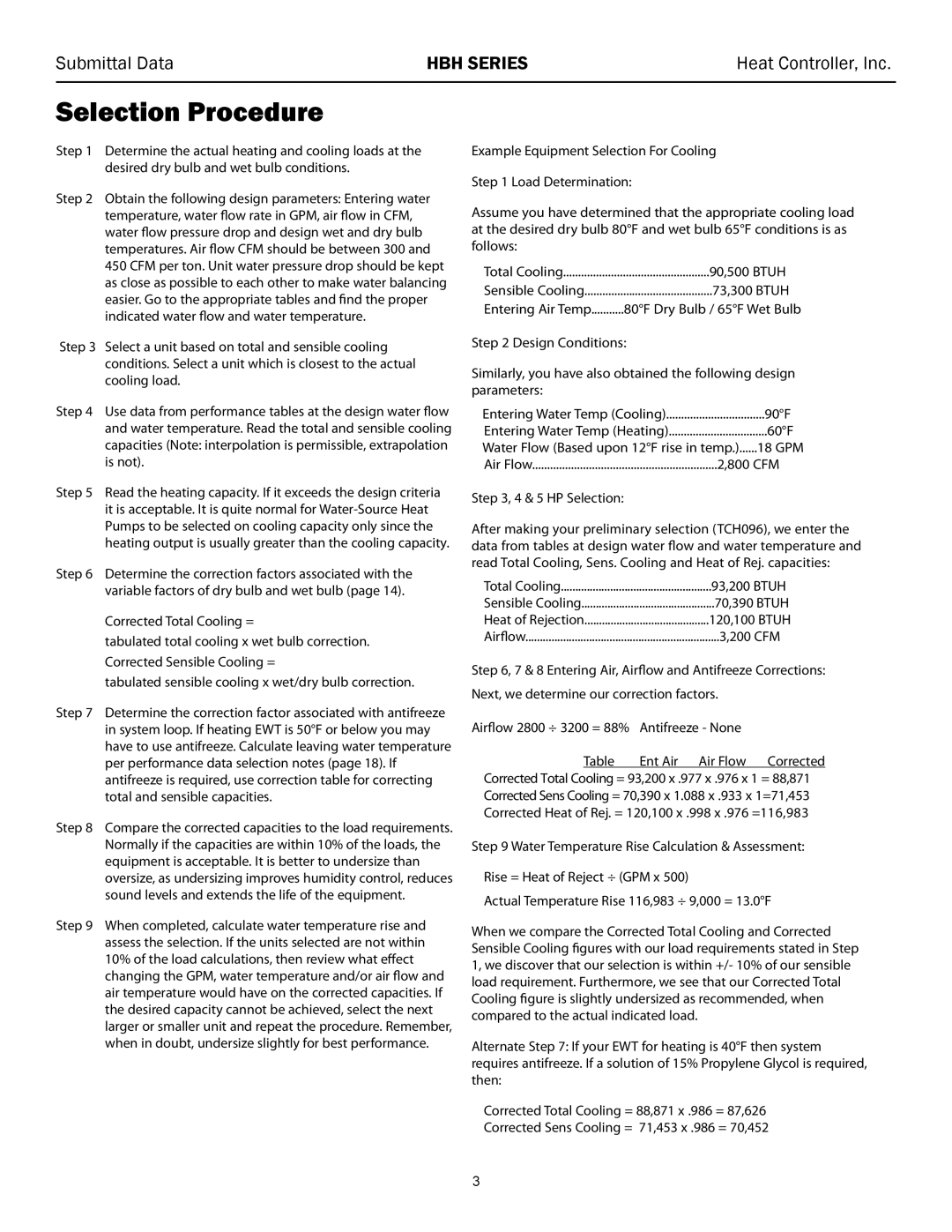
Example Equipment Selection For Cooling

Step 1 Load Determination:

Assume you have determined that the appropriate cooling load at the desired dry bulb 80°F and wet bulb 65°F conditions is as follows:

Total Cooling

90,500 BTUH

Sensible Cooling

73,300 BTUH

Entering Air Temp

80°F Dry Bulb / 65°F Wet Bulb

Step 2 Design Conditions:

Similarly, you have also obtained the following design parameters:

Entering Water Temp (Cooling)

90°F

Entering Water Temp (Heating)

60°F

Water Flow (Based upon 12°F rise in temp.)......18 GPM

Air Flow

2,800 CFM

Step 3, 4 & 5 HP Selection:

After making your preliminary selection (TCH096), we enter the data from tables at design water flow and water temperature and read Total Cooling, Sens. Cooling and Heat of Rej. capacities:

Total Cooling

93,200 BTUH

Sensible Cooling

70,390 BTUH

Heat of Rejection

120,100 BTUH

Airflow

3,200 CFM

Step 6, 7 & 8 Entering Air, Airflow and Antifreeze Corrections: Next, we determine our correction factors.

Airflow 2800 ÷ 3200 = 88%

Antifreeze - None


Table

Ent Air Air Flow Corrected

Corrected Total Cooling = 93,200 x .977 x .976 x 1 = 88,871 Corrected Sens Cooling = 70,390 x 1.088 x .933 x 1=71,453 Corrected Heat of Rej. = 120,100 x .998 x .976 =116,983

Step 9 Water Temperature Rise Calculation & Assessment:

Rise = Heat of Reject ÷ (GPM x 500)

Actual Temperature Rise 116,983 ÷ 9,000 = 13.0°F

When we compare the Corrected Total Cooling and Corrected Sensible Cooling figures with our load requirements stated in Step 1, we discover that our selection is within +/- 10% of our sensible load requirement. Furthermore, we see that our Corrected Total Cooling figure is slightly undersized as recommended, when compared to the actual indicated load.

Alternate Step 7: If your EWT for heating is 40°F then system requires antifreeze. If a solution of 15% Propylene Glycol is required, then:

Corrected Total Cooling = 88,871 x .986 = 87,626

Corrected Sens Cooling = 71,453 x .986 = 70,452

3

Page 5
Image 5
Heat Controller 60 HZR-410A 90,500 Btuh, 73,300 Btuh, Water Flow Based upon 12F rise in temp.......18 GPM, HP Selection

60 HZR-410A, HBH 072 - 120 specifications

The Heat Controller HBH 072 - 120,60 HZR-410A is a state-of-the-art heat pump designed for energy-efficient heating and cooling. This unit promises to deliver exceptional performance, making it an ideal choice for both residential and commercial applications.

One of the standout features of the HBH model is its eco-friendly refrigerant, R-410A, which helps reduce environmental impact without sacrificing performance. This refrigerant has a lower Global Warming Potential (GWP) compared to traditional refrigerants, aligning with modern environmental standards and regulations.

Power and efficiency are key aspects of the HBH 072 - 120,60. This heat pump is capable of delivering significant heating and cooling capacities, making it suitable for a wide range of spaces. The unit is equipped with advanced inverter technology, which enables it to adjust the compressor speed based on the heating or cooling demand. This results in optimal energy consumption, leading to lower utility bills while ensuring comfort throughout the year.

The HBH model integrates a high-efficiency compressor that operates quietly, providing a comfortable indoor environment without the disruptive noise often associated with traditional systems. Additionally, the unit features multiple fan speeds and a programmable thermostat, allowing users to customize their comfort settings easily.

Another highlight of this heat pump is its robust construction and weather-resistant exterior, which ensures long-lasting durability in various climatic conditions. The unit includes a built-in filter system, making maintenance hassle-free and ensuring clean air circulation within the living space.

Moreover, the HBH 072 - 120,60 HZR-410A is designed for easy installation, minimizing the downtime during the setup process. Its compact design allows for flexible placement, fitting seamlessly into various spaces without compromising aesthetics.

Safety is also a priority with this model, as it is equipped with multiple safety features, including protection against overheating and short-circuits. These enhancements not only ensure reliable operation but also provide peace of mind to users.

In summary, the Heat Controller HBH 072 - 120,60 HZR-410A heat pump stands out for its energy efficiency, advanced technology, and user-friendly features. Its combination of comfort, reliability, and eco-conscious operation makes it a prime choice for those seeking an effective heating and cooling solution.