Heat Controller, Inc. | INSTALLATION MANUAL | VMH InverterFlex |
REFRIGERANT PIPE CONNECTION
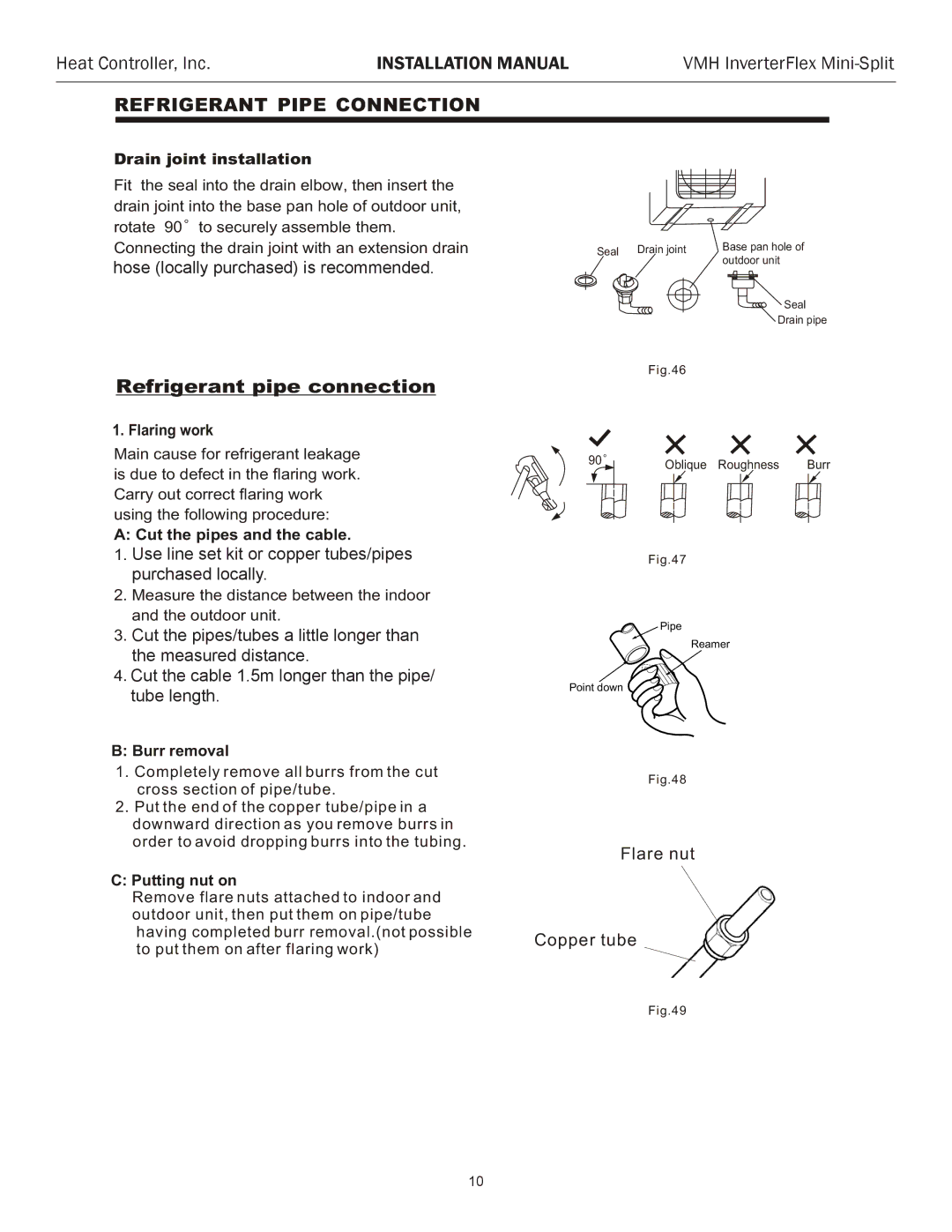
Drain joint installation
Fit the seal into the drain elbow, then insert the drain joint into the base pan hole of outdoor unit, rotate 90![]() to securely assemble them.
to securely assemble them.
Connecting the drain joint with an extension drain hose (locallyL lly purchased)), isn recommendedcase of the water. draining off the outdoor unit during the heating mode.
Seal | Drain joint | Base pan hole of |
|
| outdoor unit |
Seal |
Drain pipe
Refrigerant pipe connection
1. Flaring work
Main cause for refrigerant leakage is due to defect in the flaring work. Carry out correct flaring work using the following procedure:
A: Cut the pipes and the cable.
1.Use thelinepipingset kitkitoracoppercessorytubes/pipesor pi es purchaseded locallylocally..
2.Measure the distance between the indoor and the outdoor unit.
3.Cut tthepipes/tubesipes a little longera littlethanlongerthethan measuredthe measureddistancedistance. .
4.Cut the cablele 11.5m.5mlongerlongerthanthanthethepipipe/e tubelengthlength. .
B:Burr removal
1.Completely remove all burrs from the cut cross section of pipe/tube.
2.Put the end of the copper tube/pipe in a downward direction as you remove burrs in order to avoid dropping burrs into the tubing.
C:Putting nut on
Remove flare nuts attached to indoor and outdoor unit, then put them on pipe/tube having completed burr removal.(not possible to put them on after flaring work)
Fig.46
90 | Oblique Roughness | Burr |
Fig.47
Pipe
Reamer
Point down ![]()
![]()
Fig.48
Flare nut
Copper tube
Fig.49
10