Heat Controller, Inc. | INSTALLATION MANUAL | VMH InverterFlex |
Air Purging
and Leak Check |
|
|
|
|
Safety and leakage check |
|
|
|
|
Electrical safety check |
|
| n | m k j i h |
Perform the electric safe check after |
|
| ||
|
|
|
| |
completing installation: |
|
|
|
|
1. Insulated resistance |
| Indoor unit |
|
|
The insulated resistance must be more than |
| check point |
|
|
|
|
|
| |
2M . |
|
| f |
|
2. Grounding work | Outdoor unit | A | e |
|
After finishing grounding work, measure the | check point | B | d |
|
|
| |||
|
|
|
| |
grounding resistance by visual detection and |
|
| c |
|
| C | b |
| |
grounding resistance tester. Make sure the |
|
|
| |
|
| a |
| |
grounding resistance is less than 4 . |
|
|
|
|
3. Electrical leakage check (performing during |
|
|
|
|
test run). |
|
|
|
|
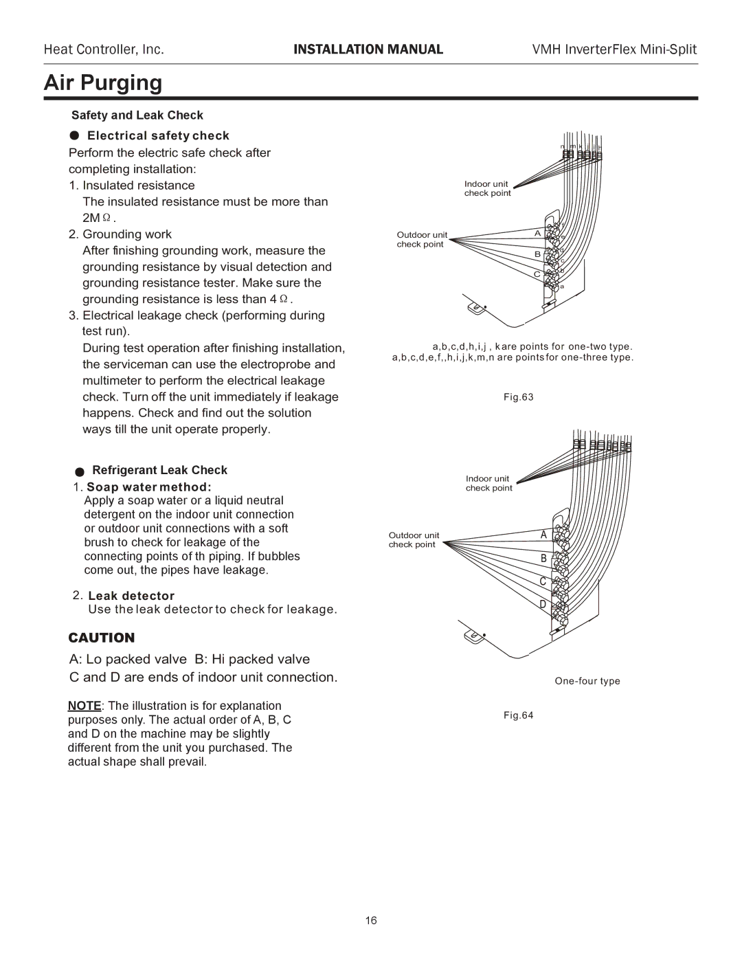
During test operation after finishing installation, | a,b,c,d,h,i,j , k are points for | |||
the serviceman can use the electroprobe and | a,b,c,d,e,f,,h,i,j,k,m,n are points for | |||
|
|
|
| |
multimeter to perform the electrical leakage |
|
|
|
|
check. Turn off the unit immediately if leakage |
| Fig.63 |
|
|
happens. Check and find out the solution |
|
|
|
|
ways till the unit operate properly. |
|
|
|
|
RefrigerantGas leak checkLeak Check
1.Soap water method:
ApplyA plyaasoapsoapwaterwateror ora liquida liquidneutralneutral detergentetergentononthetheindoorindoorunitunitconnectionconnection ororoutdooroutd orunitunitconnectionsconnectionswithbya asoftsoft brushbrushtotocheckcheckforforleakageleakageof theof the connectingconnectingpointspointsof ofth thpipingpiping. If bubbles. If bubbles comecomeout,out,thethepipesipeshavehaveleakageleakage. .
2.Leak detector
Use the leak detector to check for leakage.
Indoor unit check point
Outdoor unit check point
CAUTION
A: Lo packed valve B: Hi packed valve
C and D are ends of indoor unit connection.
NOTENOTE:: TheTheillustrationillustrationis forisexplanationfor explanation purposespurposeonlyonly. The. Theactualactualorderorderof A, B,of CA, B, C and D on the machine may be slightly
and D on the machine may be slightly different from the unit you purchased. The different from the unit you purchased. The actual shape shall prevail.
actual shape shall prevail.
Fig.64
16