VMH InverterFlex | INSTALLATION MANUAL | Heat Controller, Inc. |
|
|
|
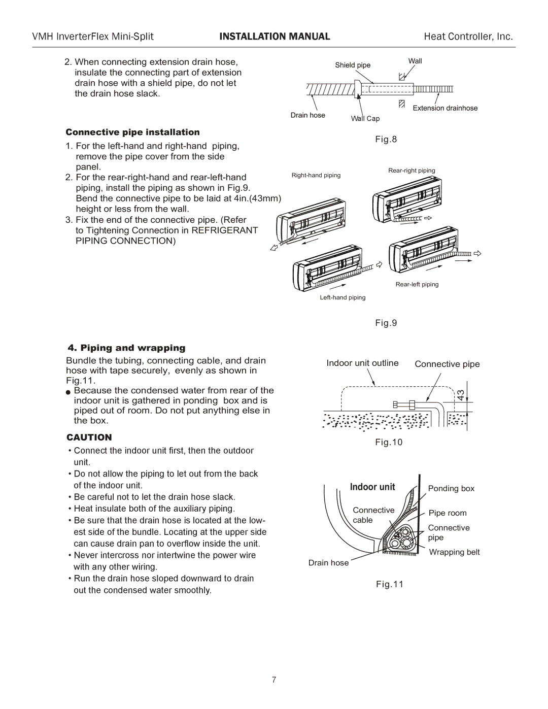
2.When connecting extension drain hose, insulate the connecting part of extension drain hose with a shield pipe, do not let the drain hose slack.
Connective pipe installation
1.For the
2.For the
Bend the connective pipe to be laid at 4in.(43mm) height or less from the wall.
3. Fix the end of the connective pipe. (Refer to Tightening Connection in REFRIGERANT PIPING CONNECTION)
Wall Cap
Fig.8
![]()
![]()
![]()
4. Piping and wrapping
Bundle the tubing, connecting cable, and drain hose with tape securely, evenly as shown in Fig.11.
![]() Because the condensed water from rear of the indoor unit is gathered in ponding box and is piped out of room. Do not put anything else in the box.
Because the condensed water from rear of the indoor unit is gathered in ponding box and is piped out of room. Do not put anything else in the box.
CAUTION
• Connectectthetheindoorindoorunitunitfirst,first,thenthenthe outdoorthe
outdoorunit. unit.
Do not allow the piping to let out from
• Do not allow the piping to let out from the back the back of the indoor unit.
of the indoor unit.
Be careful not to let the drain hose slack.
• Be careful not to let the drain hose slack. Heat insulated both of the auxiliary piping.
• BeHeatsureinsulatethat boththe drainof the hoseauxiliaryis locatedpiping. at
•theBe surelowestthatsidethe drainof thehosebundleis located. Locatingat the low- atest thesideupperof the bundleside can. Locatinguse atdrainthe upperpan side to overflow inside the unit.
can cause drain pan to overflow inside the unit.
Never intercross nor intertwist the power
•Never intercross nor intertwine the power wire wire with any other wiring.
with any other wiring.
Run the drain hose sloped downward to
•drainRun theoutdrainthehosecondensedsloped downwardwater smoothlyto drain. out the condensed water smoothly.
Fig.9
Indoor unit outline |
| Connective pipe | ||||||||||||||||||||
|
|
|
|
|
|
|
|
|
|
|
|
|
|
|
|
|
|
|
| 43 | ||
. |
|
|
|
|
|
| . . | .. . . . |
| . |
|
|
| . | ||||||||
. . | . |
|
|
|
|
| .. |
|
| . |
|
|
|
| .. | |||||||
. |
|
|
|
| .. |
|
| .. . |
| . . | . |
|
|
| ||||||||
|
| ... | . |
| . |
| . . .. |
|
| . |
| |||||||||||
|
|
|
|
|
| . . |
|
| .. |
| ||||||||||||
|
| . .... |
|
|
|
| . . | . |
|
| ||||||||||||
| . . . ..... | . . ... |
|
| . | .. .. | ||||||||||||||||
|
|
|
|
|
|
|
|
| . . |
| . |
|
|
|
|
|
|
|
| |||
|
| .. . . |
|
| . |
| . . . . |
|
|
|
|
|
|
| ||||||||
. . . |
|
| . . . . . . . |
|
|
|
|
|
|
|
|
| ||||||||||
. . |
|
|
|
|
|
|
|
|
|
|
|
| ||||||||||
. |
|
| . | . |
|
|
|
|
|
|
|
|
|
|
|
|
|
|
|
|
| |
|
|
|
|
|
|
|
| Fig.10 |
|
|
|
|
|
|
|
|
|
| ||||
|
|
|
|
|
|
|
|
|
|
|
|
|
|
|
|
|
|
|
| |||
|
|
|
|
|
| Indoor unit |
|
|
|
|
| Ponding box | ||||||||||
|
|
|
|
|
| Connective |
|
|
|
|
| Pipe room | ||||||||||
|
|
|
|
|
| cable |
|
|
|
|
|
|
| Connective | ||||||||
|
|
|
|
|
|
|
|
|
|
|
|
|
|
|
|
|
| |||||
|
|
|
|
|
|
|
|
|
|
|
|
|
|
|
|
|
| pipe |
|
|
|
|
Drain hose |
|
|
|
|
|
|
|
|
|
|
|
| Wrapping belt | |||||||||
|
|
|
|
|
|
|
|
|
|
|
|
|
|
|
|
| ||||||
Fig.11
7