
SL-5210 specifications
The Heath Zenith SL-5210 is a state-of-the-art motion-activated light fixture designed to enhance both security and convenience around residential properties. With its cutting-edge features, this outdoor security light has become a favorite among homeowners looking for reliable illumination and safety.One of the standout characteristics of the SL-5210 is its advanced motion detection technology. Equipped with a passive infrared (PIR) sensor, this light can detect movement from up to 70 feet away, providing a broad coverage area. This capability allows it to monitor driveways, walkways, and other key points of entry, ensuring that any movement is promptly illuminated.
The SL-5210 also offers adjustable settings that allow users to customize the light’s sensitivity, duration, and the range of detection. Users can easily modify the time the light stays on after detecting motion, adjusting it from a short burst of light to several minutes, based on their needs. The sensitivity settings are also user-friendly, enabling adjustments based on environmental factors, ensuring that the light is triggered only when necessary.
Energy efficiency is another key feature of the Heath Zenith SL-5210. Utilizing LED bulbs, this light is designed to provide bright illumination while consuming minimal power. LEDs have a significantly longer lifespan compared to traditional incandescent bulbs, contributing to lower energy bills and reduced maintenance costs.
Durability is a significant consideration for any outdoor fixture, and the SL-5210 does not disappoint. Constructed with high-quality materials, it is weather-resistant, allowing it to withstand various outdoor elements, including rain, wind, and extreme temperatures. This rugged design ensures that it can provide reliable service year-round.
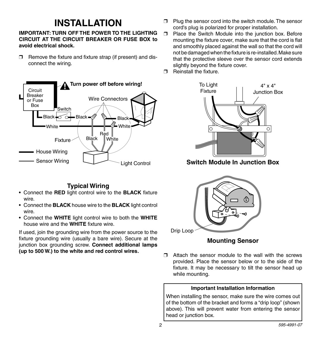
The installation process for the SL-5210 is straightforward, as it comes with all necessary hardware and a clear installation guide. This accessibility empowers homeowners to set up the security light with ease, enhancing the overall user experience.
In summary, the Heath Zenith SL-5210 motion-activated light fixture combines advanced motion detection technology, energy efficiency, customizability, and robust durability. It is an ideal solution for enhancing residential security while providing reliable illumination for outdoor areas. Homeowners seeking a dependable outdoor lighting solution will find that the SL-5210 meets and exceeds their expectations.