
SL-5309 specifications
The Heath Zenith SL-5309 is an innovative motion sensor security light designed to enhance outdoor safety and convenience. This smart lighting solution combines advanced technology with user-friendly features, making it an ideal addition to residential properties.One of the standout features of the SL-5309 is its dual-brightness functionality. It can emit a soft glow during low-light conditions, activating to full brightness when motion is detected. This not only conserves energy but also provides users with a welcoming light that automatically intensifies when needed, ensuring safety without being overly obtrusive.
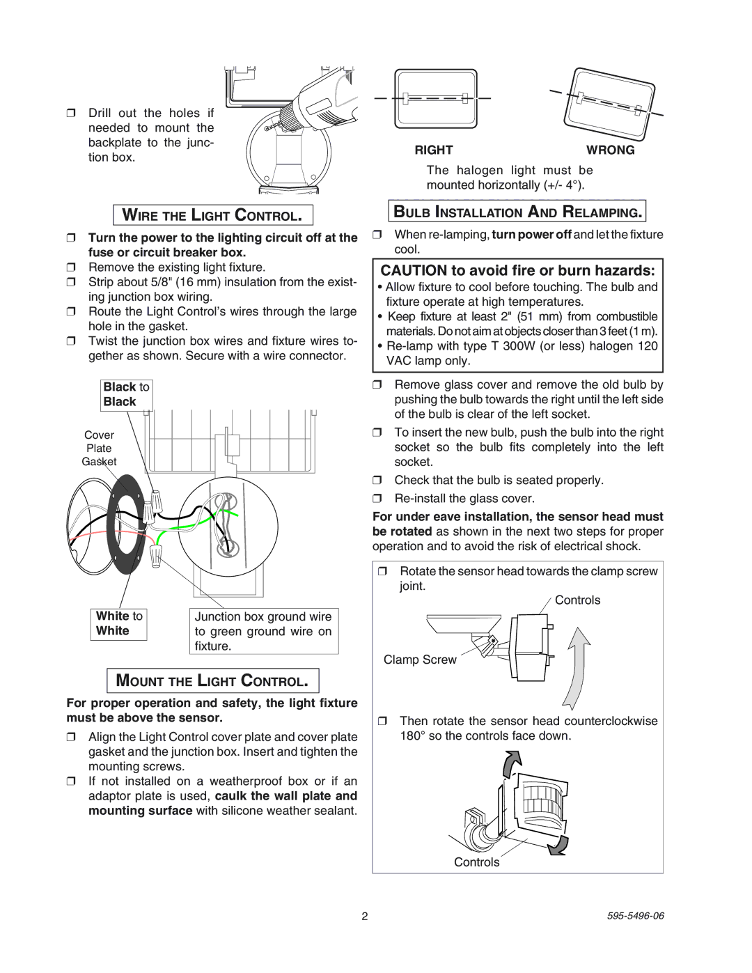
The motion sensor capabilities of the SL-5309 are powered by passive infrared (PIR) technology, which allows the device to detect movement within a specified range. The adjustable detection settings enable users to customize the sensor's sensitivity and the distance at which it responds to motion, providing flexibility based on individual requirements and outdoor layouts. With a detection range of approximately 180 degrees and up to 30 feet, the SL-5309 ensures a broad coverage area, enhancing the security of homes and properties.
Another notable characteristic of the Heath Zenith SL-5309 is its weather-resistant design. Made with durable materials, this outdoor light is built to withstand various environmental conditions, including rain, snow, and extreme temperatures. Its robust construction ensures long-lasting performance, making it a reliable choice for outdoor lighting.
Installation of the SL-5309 is straightforward, as it features a simple mounting system that allows users to secure the light in various outdoor locations, such as driveways, patios, or entryways. The product comes with necessary hardware and a user-friendly manual, ensuring a hassle-free setup process.
Additionally, the Heath Zenith SL-5309 incorporates an energy-efficient LED bulb that not only offers bright illumination but also reduces power consumption compared to traditional lighting sources. LED technology promotes longevity and decreases the need for frequent bulb replacements, making the SL-5309 an eco-friendly choice.
Overall, the Heath Zenith SL-5309 is a versatile and efficient outdoor lighting solution. With its intelligent motion sensing, adjustable settings, weather-resistant design, and energy-efficient LED, this security light enhances both safety and convenience for homeowners. Whether illuminating dark pathways or providing security after dark, the SL-5309 stands out as a reliable and stylish addition to any outdoor space.