Manuals
/
Henny Penny
/
Kitchen Appliance
/
Fryer
Henny Penny
OFE-321
manual
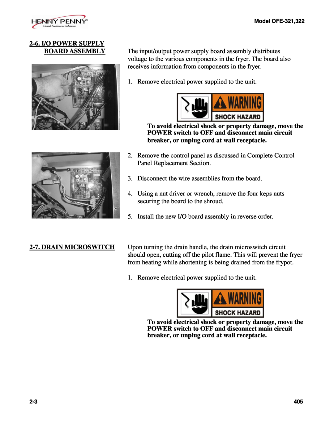
2-6.I/O POWER SUPPLY
Models:
OFE-321
1
3
14
14
Download
14 pages
56.45 Kb
1
2
3
4
5
6
7
8
Maintenance
Speaker Assembly
Replacement
2-6.I/O POWER SUPPLY
Filter Switch
Page 3
Image 3
Page 2
Page 4
Page 3
Image 3
Page 2
Page 4
Contents
SECTION 2. MAINTENANCE
2-3.COMPLETE CONTROL
2.Remove control panel
2-6.I/O POWER SUPPLY
2-8.FILTER SWITCH
2-7.DRAIN MICROSWITCH Continued
Voltage
Replacement
2-9.HEATING ELEMENTS
Checkout
Temperature Spreader Probe
14. Replace the shortening in the frypot
Checkout Power Removed
2-10.HEATING CONTACTORS 3031 33
Mercury Contactor
Continued
Checkout Power Supplied
2-10.HEATING
CONTACTORS
2-12.HIGH TEMPERATURE
2-11.SPEAKER ASSEMBLY
1.Drain the shortening from the frypot
14.Replace front panel 15.Refill with shortening
2-12.HIGH TEMPERATURE LIMIT CONTROL Continued
2-13
2-14
Top
Page
Image
Contents