32PD5000 42PD5000
Features
Contents
About the Symbols
Safety Instructions
Be cautious of the power cord connection
Be sure to keep safety ground connection
Be careful in handling the battery of the remote control
Safety Instructions
Precaution during transportation
Precautions for the cable connection
Do not physically impact the remote control
Set the sound volume at a suitable level
Main Unit
Component Names
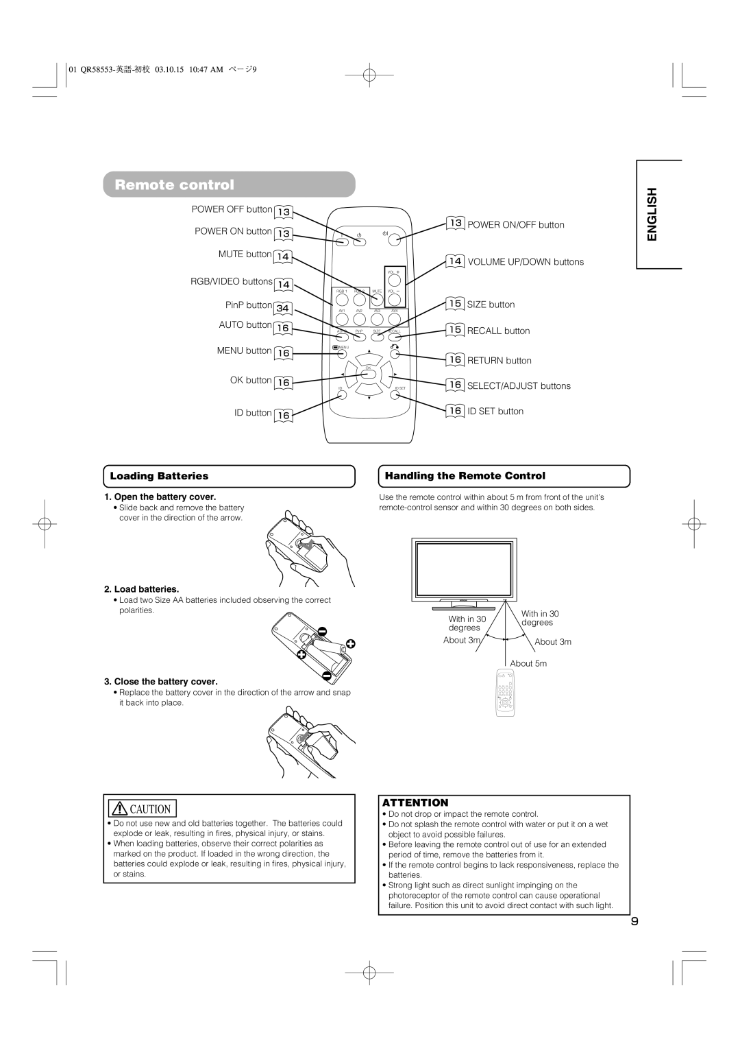
Remote control
Handling the Remote Control
Loading Batteries
Installation
Installation Instructions
Anti-tumble measures
Securing to a wall or pillar
Monitor rear panel
Connecting to a PC
01 QR58553-英語-初校03.10.15 1047 AM ページ12
Turning Power On and Off
Operating Instructions
Indicating lamp
Input Switching
Operating Instructions Volume Adjustment
When a button is pressed, the volume adjustment
Audio Mute
Size Switching
Input Signal Screen Display
Display area selection diagram RGB input
Automatic Adjustment of Screen Position and the Clock
Using the Menu Screen On-screen display system
Operating Instructions
Independent Operation of Multiple Monitors ID No
Picture Menu
Off Timer Min 30Min 60Min 120Min 90Min On Timer
Timer Menu
Audio Menu
Movie Music Speech Favorite
Function Menu
Movie
Setup Menu
Language Menu
Other Features
Automatic Store
Menu Display Registration condition
Power Save Mode
Other Features Signal Check
When the RGB1, RGB2 input is selected
Status Display Action
Methods to Reduce the Occurrence of Image Retention
Image Retention of Plasma Display
About screen defects
About residual images
Symptoms That Seemingly Appear to be Failures
Troubleshooting
Check the way the signal cable is connected
Check to see if the input signal matches the monitor
01 QR58553-英語-初校03.10.15 1047 AM ページ25
Example
Troubleshooting Actions to Correct Abnormal Displays
Signal Input
Product Specifications
RGB terminal D-sub 15-pin connector
Pin Input signal
Recommended Signal List
Product Specifications Signal Input
With Digital RGB signal input RGB1 input
DVI terminal DVI-D
XGA
With Analog RGB signal input RGB2 input
Supplement
An example of connecting video imaging devices
Connecting to a Video Imaging Device
With RGB component setup
Optional Video Unit Function
When you want to
Display size selection diagram
Input signal Display screen Remarks
AV1 AV2 AV3 RGB2 RGB1 AV4
Press
Using a wide-screen monitor
Pictures Split
Operating Instructions Displaying Multi Picture
01 QR58553-英語-初校03.10.15 1047 AM ページ35
Operating Instructions Picture Menu
Film Mode PAL Comb Filter
Black Enhancement Auto Color
Red
Magenta
Color Management
Cyan
Color Decoding
System Color System
Video Input
AV2 1st step AV2 2nd step
Scart Output
Audio Input
RGB2 1st step
RGB2 2nd step
01 QR58553-英語-初校03.10.15 1047 AM ページ40
Input connector pin specifications
Scart connector pin specifications
Not Used
With R, G, B Video input AV2 and AV4 input
Product Specifications Recommended Signal List
With component input AV1, AV2 and RGB2-component input
KHz MHz
Optional Tuner Unit Function
Remote control provided for the optional tuner unit
Picture mode is changed in following
You may recall the picture mode by
Press this button to change input Surround On or Off Mode
Pressing this button. Each time pressed
Buttons for Teletext Mode
Connecting Antenna
Precautions when connecting the antenna
Monitor rear panel
Panoramic Full Cinema Zoom
TV AV1 AV2 AV3 RGB2 RGB1 AV4
Activating the Split mode from the TV screen
Multi Picture button Multi Mode button Button
Pictures Split 4 pictures 12 pictures
Off-timer
Sound mode
Pictures
Name
Freeze button
Picture Freezing
Split Strobe
Split Strobe Panoramic
Abcde
During TV mode
Operating Instructions Setup Menu
During Video signal input
Auto Off
A2 / Nicam / Sound Multiplex
Other Functions
Bilingual / Dual sound broadcast
Stereo sound broadcast
SUB page buttons Reveal button Cancel button
Mode button Index button TV / Text button
Operating Instructions Other Functions
DVD Player Selection
Multiple images sound O.K
Snowy picture poor sound
Intermittent interference
No picture or sound
01 QR58553-英語-初校03.10.15 1047 AM ページ56
Speaker holder Speakers Speaker cable with core
Application Model 42PD5000*,42PMA500*,42HDM70,CMP421
Mounting screw
Cushions
Attach the speaker brackets to the speaker systems
Attach the speaker systems to the monitor
Modèle applicable 42PD5000*, 42PMA500*, 42HDM70, CMP421
Vis de montage
Coussin
Pour bien immobiliser le dispositif
Fixer les haut-parleurs sur l’écran
Geeignetes Modell 42PD5000*,42PMA500*,42HDM70,CMP421
Lautsprecherhalterung Lautsprecherkabel mit Ader
Polster 2 Befestigungsschraube
Verwendung von Polstern
Bringen Sie die Lautsprecherbügel am Monitor an
Bringen Sie die Lautsprecherverbindungskabel
Behandlung der Drahtenden
Potenza massima d’ingresso
Attenzione
Fissare il sistema audio allo schermo
Uso degli ammortizzatori
Come illustrato e tenerle per il ri
Altavoces bidireccionales
Modelo Aplicable 42PD5000*,42PMA500*,42HDM70,CMP421
Apriete firmemente los cuatro tornillos
Abajo. Seguidamente, use los tornillos
Högtalarhållare Högtalare Högtalarkabel med kärna
Monteringsskruvar
Vibrationsdämpare
Montering av högtalarsystemet på skärmen
Om vibrationsdämparna
Anslutningskärmen
Brukermodell 42PD5000*,42PMA500*,42HDM70,CMP421
Høytalerholder Høytalere Høytalerkabel med kjerne
Puten 2 stk Monteringsskrue
Skyv inn de to løsnede skruene inn
Monter høytalersystemene til monitoren
Feste høytalerholderene til skjermen
Behandle trådendene
簡体中文
00 42型スピーカー統合-五校03.9.9 339 PM ページ16
繁體中文
00 42型スピーカー統合-五校03.9.9 339 PM ページ18
CMPAS14/CMPAS14S 取扱説明書
お知らせ