CONNECTING EXTERNAL AUDIO SOURCES
TIME USE
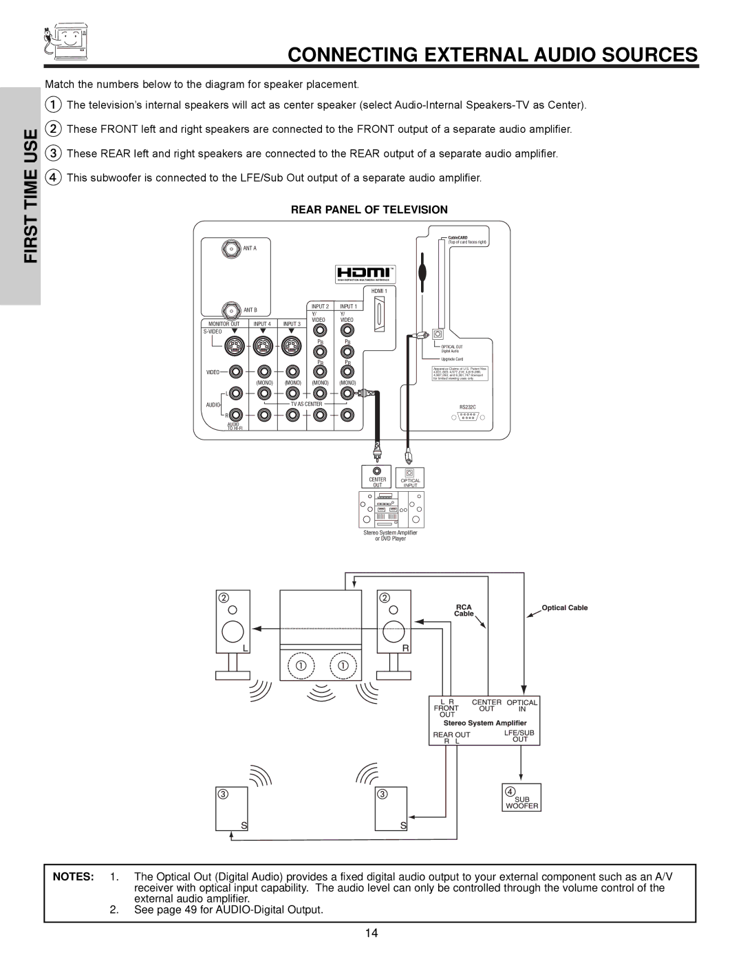
Match the numbers below to the diagram for speaker placement.
The television’s internal speakers will act as center speaker (select
These FRONT left and right speakers are connected to the FRONT output of a separate audio amplifier.
These REAR left and right speakers are connected to the REAR output of a separate audio amplifier.
This subwoofer is connected to the LFE/Sub Out output of a separate audio amplifier.
REAR PANEL OF TELEVISION
FIRST
ANT A
HDMI 1
| ANT B |
| INPUT 2 | INPUT 1 |
|
| Y/ | Y/ | |
|
|
| ||
MONITOR OUT | INPUT 4 | INPUT 3 | VIDEO | VIDEO |
|
| |||
|
|
|
| |
|
|
| PB | PB |
|
|
| PR | PR |
VIDEO |
|
|
|
|
| (MONO) | (MONO) | (MONO) | (MONO) |
L |
|
|
|
|
AUDIO |
| TV AS CENTER |
| |
R |
|
|
|
|
AUDIO
TO
 CableCARD
(Top of card faces right)
 OPTICAL OUT
Digital Audio
Upgrade Card
Apparatus Claims of U.S. Patent Nos. 4,631,603; 4,577,216; 4,819,098; 4,907,093; and 6,381,747 licensed for limited viewing uses only.
RS232C
1 2 3 4 5
6 7 8 9
CENTER |
|
|
|
OPTICAL | |||
OUT | INPUT | ||
Stereo System Amplifier
or DVD Player
NOTES: 1. The Optical Out (Digital Audio) provides a fixed digital audio output to your external component such as an A/V receiver with optical input capability. The audio level can only be controlled through the volume control of the external audio amplifier.
2.See page 49 for
14