English
APPLICATIONS
Cleans screen doors, window glass, floors, walls, etc. Cleans automobiles, motorbikes, etc.
Cleans mud o![]() gardening equipment and agricultural equipment.
gardening equipment and agricultural equipment.
PRIOR TO OPERATION
1.Installation of an earth leakage circuit breaker
It is recommended that an earth leakage circuit breaker is connected to the washer to shut o![]() the power if leaking current exceeds 30 mA for 30 milliseconds in order to prevent electric shocks.
the power if leaking current exceeds 30 mA for 30 milliseconds in order to prevent electric shocks.
2.Keep the work area neat and tidy
Dirty water will be sprayed about when using the washer. It is therefore necessary to check the area to make sure there are no hindrances, and keep the work area neat and tidy.
3.Situating the washer
Select flat locations where the washer will not be splashed with water when cleaning.
4.Using extension cords
Make sure the cord is thick enough to provide a constant supply of electricity, and use cords that are as short as possible.
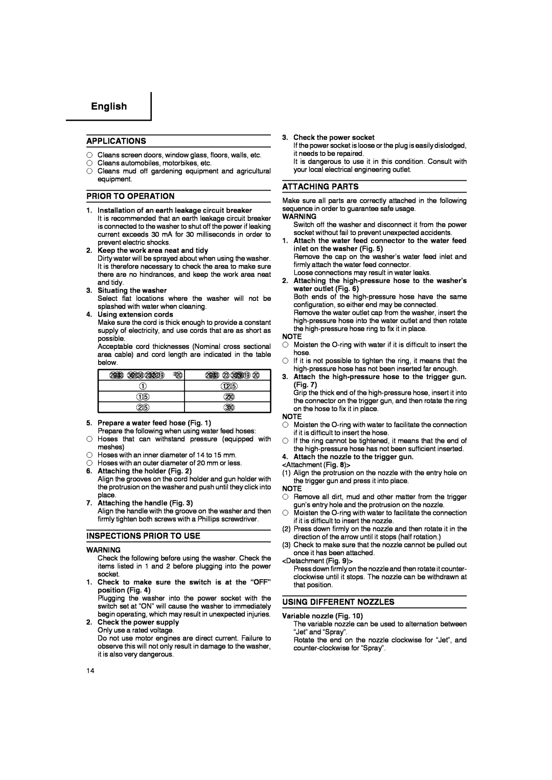
Acceptable cord thicknesses (Nominal cross sectional area cable) and cord length are indicated in the table below.
ݱ®¼Ô»²¹¬¸ø³÷ |
ïïîòë
ïòë | îð |
îòë | íð |
5. Prepare a water feed hose (Fig. 1)
Prepare the following when using water feed hoses:
Hoses that can withstand pressure (equipped with meshes)
Hoses with an inner diameter of 14 to 15 mm.
Hoses with an outer diameter of 20 mm or less.
6. Attaching the holder (Fig. 2)
Align the grooves on the cord holder and gun holder with the protrusion on the washer and push until they click into place.
7. Attaching the handle (Fig. 3)
Align the handle with the groove on the washer and then firmly tighten both screws with a Phillips screwdriver.
INSPECTIONS PRIOR TO USE
WARNING
Check the following before using the washer. Check the items listed in 1 and 2 before plugging into the power socket.
1. Check to make sure the switch is at the “OFF” position (Fig. 4)
Plugging the washer into the power socket with the switch set at “ON” will cause the washer to immediately begin operating, which may result in unexpected injuries.
2. Check the power supply Only use a rated voltage.
Do not use motor engines are direct current. Failure to observe this will not only result in damage to the washer, it is also very dangerous.
3.Check the power socket
If the power socket is loose or the plug is easily dislodged, it needs to be repaired.
It is dangerous to use it in this condition. Consult with your local electrical engineering outlet.
ATTACHING PARTS
Make sure all parts are correctly attached in the following sequence in order to guarantee safe usage.
WARNING
Switch o![]() the washer and disconnect it from the power socket without fail to prevent unexpected accidents.
the washer and disconnect it from the power socket without fail to prevent unexpected accidents.
1. Attach the water feed connector to the water feed inlet on the washer (Fig. 5)
Remove the cap on the washer’s water feed inlet and firmly attach the water feed connector.
Loose connections may result in water leaks.
2. Attaching the
Both ends of the
NOTE
Moisten the ![]() cult to insert the hose.
cult to insert the hose.
If it is not possible to tighten the ring, it means that the
3. Attach the
Grip the thick end of the
NOTE
Moisten the ![]() cult to insert the hose.
cult to insert the hose.
If the ring cannot be tightened, it means that the end of the ![]() cient inserted.
cient inserted.
4. Attach the nozzle to the trigger gun. <Attachment (Fig. 8)>
(1) Align the protrusion on the nozzle with the entry hole on the trigger gun and press it into place.
NOTE
Remove all dirt, mud and other matter from the trigger gun’s entry hole and the protrusion on the nozzle. Moisten the ![]() cult to insert the nozzle.
cult to insert the nozzle.
(2) Press down firmly on the nozzle and then rotate it in the direction of the arrow until it stops (half rotation.)
(3) Check to make sure that the nozzle cannot be pulled out once it has been attached.
<Detachment (Fig. 9)>
Press down firmly on the nozzle and then rotate it counter- clockwise until it stops. The nozzle can be withdrawn at that position.
USING DIFFERENT NOZZLES
Variable nozzle (Fig. 10)
The variable nozzle can be used to alternation between “Jet” and “Spray”.
Rotate the end on the nozzle clockwise for “Jet”, and
14