Function List

[ : Allowed ]

H Group: Motor constants functionsX: Not allowed


Default


Run mode

Function Code


Name

Range

-EF(CE) -U(UL)

-R(JP)

Unit


edit


Lo

Hi


H003

Motor capacity, 1st motor

0.2/0.4/0.55/0.75/1.1/1.5/2.2/3.0/4.0/5.5

Factory Factory Factory

kW

X

X


H203

Motor capacity, 2nd motor

set

set

set

kW

X

X


Motor constants and

H004

Motor poles setting, 1st motor

2/4/6/8

4

4

4

poles

X

X

gain

H204

Motor poles setting, 2nd motor

4

4

4

poles

X

X


H006

Motor stabilization constant, 1st motor

0. to 255.

100

100

100

%


H206

Motor stabilization constant, 2nd motor

100

100

100

%


P Group: Expansion Card Functions


[X:: NotAllowedallowed ]


Default


Run mode

Function Code


Name

Range

-EF(CE)

-U(UL)

-R(JP)

Unit


edit


Lo


Hi


P044

Network comm watchdog timer

0.00 to 99.99

1.00

1.00

1.00

sec.

X


X


P045

Inverter action on network comm error

00(Trip (Error Code E70)) 01(Decelerate to stop and trip (Error Code E70))

01

01

01

-

X


X


02(Hold last speed), 03(Free run stop), 04(Decelerate and stop)


P046

Polled I/O output instance number

20/21/100

21

21

21

-

X


X

Option Setting


P047

Polled I/O input instance number

70/71/101

71

71

71

-

X


X


00(Trip (Error Code E70))


P048

Inverter action on network idle mode

01(Decelerate to stop and trip (Error Code E70))

01

01

01

-

X


X


02(Hold last speed), 03(Free run stop), 04(Decelerate and stop)


P049

Network motor poles setting for RPM

00 to 38

0

0

0

-

X


X

Note: The "P" Group parameters do not appear in the parameter list shown on the keypad display unless the expansion card is installed on the inverter.

Protective Functions

Error Codes

Name

Cause(s)


Display on digital

Display on remote


operator

operator/copy unit


While at


OC.Drive


constant speed


During


The inverter output was short-circuited, or the motor shaft is locked or has a heavy


OC.Decel


deceleration


Over current

load. These conditions cause excessive current for the inverter, so the inverter


During


output is turned OFF.


OC.Accel


acceleration


Others


Over.C


Overload

When a motor overload is detected by the electronic thermal function, the inverter trips and turns OFF


Over.L


protection *1

its output.


Over voltage protection


When the DC bus voltage exceeds a threshold, due to regenerative energy from the motor.


Over.V


EEPROM error *2,3

When the built-in EEPROM memory has problems due to noise or excessive temperature, the inverter


EEPROM


trips and turns OFF its output to the motor.


Under-voltage error

A decrease of internal DC bus voltage below a threshold results in a control circuit fault. This condition


Under.V


can also generate excessive motor heat or cause low torque. The inverter trips and turns OFF its output.


CPU error

A malfunction in the built-in CPU has occurred, so the inverter trips and turns OFF its output to the


CPU


motor.


External trip

A signal on an intelligent input terminal configured as EXT has occurred. The inverter trips and turns


EXTERNAL


OFF the output to the motor.


When the Unattended Start Protection (USP) is enabled, an error occurred when power is applied while a


USP *4


USP


Run signal is present. The inverter trips and does not go into Run Mode until the error is cleared.


Ground fault *5

The inverter is protected by the detection of ground faults between the inverter output and the motor


GND.Flt


during powerup tests. This feature protects the inverter, and does not protect humans.


When the input voltage is higher than the specified value, it is detected 100 seconds after powerup


Input over-voltage


OV.SRC


and the inverter trips and turns OFF its output.


When the inverter internal temperature is above the threshold, the thermal sensor in the inverter module


Inverter thermal trip


OH FIN


detects the excessive temperature of the power devices and trips, turning the inverter output OFF.


An internal inverter error has occurred at the safety protection circuit between the CPU and main driver


Driver error


DRIV


unit. Excessive electrical noise may be the cause. The inverter has turned OFF the IGBT module output.


When a thermistor is connected to terminals [PTC] and [CM1] and the inverter has sensed the


Thermistor


TH


temperature is too high, the inverter trips and turns OFF the output.


Safety Stop

Safety stop signal given.


EMERGENCY


Communications error

The inverter's watchdog timer for the communications network has timed out.

COMM

Note 1: Reset operations acceptable 10 seconds after the trip. Note 2: If an EEPROM error (E08) occurs, be sure to confirm the parameter data values are still correct.

Note 3: EEPROM error may occer at power-on after shutting down the power while copying data with remote operator or initializing data. Shut down the power after completing copy or initialization.

Note 4: USP error occures at reseting trip after under-voltage error (E09) if USP is enabled. Reset once more to recover.

Note 5: Ground fault error (E14) cannot be released with resetting. Shut the power and check wiring.

How to access the details about the present fault

1

2

Error code

Output frequency

at trip point


1 2

1

2

1

2

1

2

Motor current


Voltage between


Cumulative inverter

Cumulative power-on

at trip point

P(+) and N(-) at trip point


RUN time at trip point

time at trip point

1

2

10


Page 11
Image 11
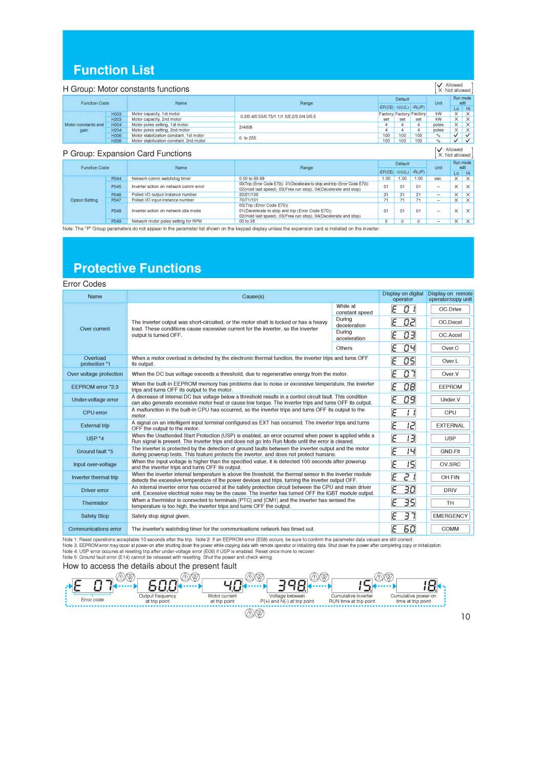
Hitachi X200 manual Protective Functions, Group Motor constants functionsX Not allowed, Group Expansion Card Functions

X200 specifications

The Hitachi X200 series is a line of cutting-edge industrial drives designed to enhance operational efficiency and performance across various applications. Developed with advanced technologies, the X200 drives are geared toward providing seamless integration, superior control, and robust reliability in manufacturing environments.

One of the standout features of the Hitachi X200 is its exceptional control capabilities. The drive employs vector control technology, enabling precise and efficient motor control across a range of speeds. This allows users to achieve optimal performance in applications that require a high level of accuracy and responsiveness. The built-in auto-tuning function simplifies the setup process, adjusting parameters automatically to ensure that the drive operates at its best.

Another key characteristic of the X200 series is its energy efficiency. The drives are designed to minimize energy consumption while maximizing output. With features like energy-saving mode and advanced power management, operators can significantly reduce operational costs. This focus on sustainability is becoming increasingly important as industries strive to meet environmental regulations and improve their carbon footprint.

The X200 series also showcases robust communication capabilities. It supports multiple communication protocols, including Modbus, Profibus, and Ethernet/IP. This flexibility ensures that users can easily integrate the drives into existing automation systems and communicate seamlessly with other devices. Additionally, the drive supports remote monitoring and control, allowing for real-time performance tracking and adjustments from anywhere.

Reliability is paramount in industrial settings, and the Hitachi X200 does not disappoint. It is built with high-quality components that ensure durability and longevity even in harsh operating conditions. The drives have a wide operational temperature range and are designed to withstand vibrations, making them suitable for challenging environments.

Furthermore, the X200 series comes equipped with advanced safety features, including built-in motor overload protection and fault diagnosis capabilities. This ensures that any potential issues are identified promptly, minimizing downtime and improving overall reliability.

In conclusion, the Hitachi X200 series offers a comprehensive solution for industries looking to enhance their motor control and automation capabilities. With its advanced control technologies, energy efficiency, robust communication options, and high reliability, the X200 drives stand out as a top choice for modern industrial applications. These features combine to deliver not just performance but also a pathway toward greater operational efficiency and sustainability.