Manuals
/
Brands
/
Power Tools
/
Welding System
/
Hobart Welding Products
/
Power Tools
/
Welding System
Hobart Welding Products
OM-949
SECTION 8 PARTS LIST
1
32
36
36
Download
36 pages, 885.88 Kb
OM-949 Page 28
SECTION 8
−
PARTS LIST
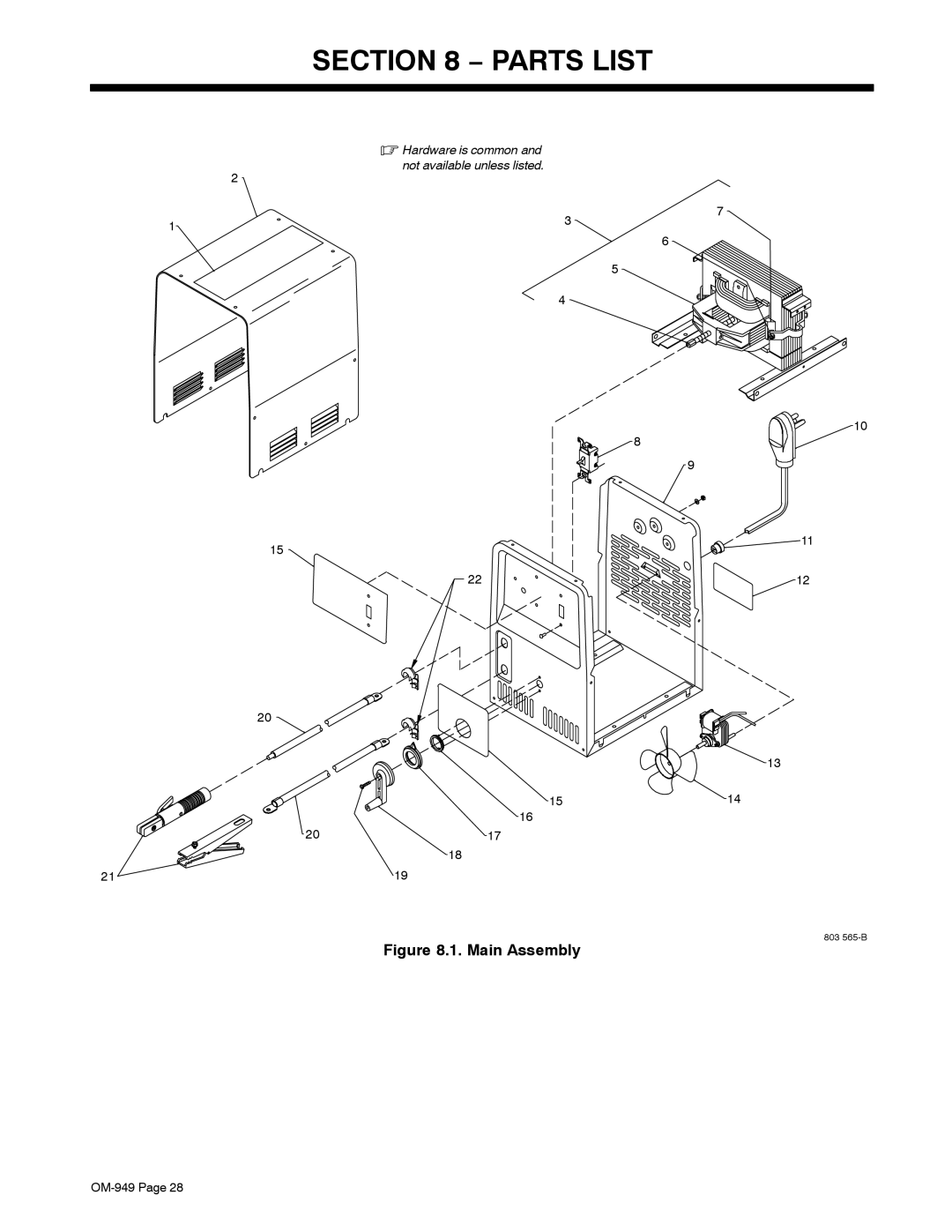
Figure 8.1. Main Assembly
803 565-B
.
Hardware is
common and
not available unless listed.
19
6
5
7
4
3
8
21
11
15
20
20
18
17
16
15
14
13
12
10
9
2
1
22
Contents
Main
From Hobart to You
TABLE OF CONTENTS
Page
SECTION 1 SAFETY PRECAUTIONS - READ BEFORE USING
1-1. Symbol Usage
.
1-2. Arc Welding Hazards
ELECTRIC SHOCK can kill.
ARC RAYS can burn eyes and skin.
WELDING can cause fire or explosion.
FLYING METAL can injure eyes.
BUILDUP OF GAS can injure or kill.
HOT PARTS can cause severe burns.
1-3. Additional Symbols For Installation, Operation, And Maintenance
FIRE OR EXPLOSION hazard.
FALLING UNIT can cause injury.
OVERUSE can cause OVERHEATING
STATIC (ESD) can damage PC boards.
1-5. Principal Safety Standards
1-6. EMF Information
SECTION 2 CONSIGNES DE SCURIT LIRE AVANT UTILISATION
2-1. Symboles utiliss
.
2-2. Dangers relatifs au soudage la rc
UNE DCHARGE LECTRIQUE peut entraner la mort.
LES RAYONS DARC peuvent entra- ner des brlures aux yeux et la peau.
LE SOUDAGE peut provoquer un incendie ou une explosion.
DES PARTICULES VOLANTES peuvent blesser les yeux.
LES ACCUMULATIONS DE GAZ risquent de provoquer des blessures ou mme la mort.
DES PICES CHAUDES peuvent provoquer des brlures graves.
2-3. Dangers supplmentaires en relation avec linstallation, le fonctionnement et la maintenance
Risque DINCENDIE OU DEXPLO- SION.
LA CHUTE DE LAPPAREIL peut blesser.
LEMPLOI EXCESSIF peut SUR- CHAUFFER LQUIPEMENT.
LES CHARGES LECTROSTATIQUES peuvent endommager les circuits imprims.
2-5. Principales normes de scurit
2-6. Information EMF
SECTION 3 INSTALLATION
3-1. Specifications
Output Amperage
% Duty Cycle
3-2. Duty Cycle Charts
3-3. Volt-Ampere Curves
Volts
Amps
230 Volt Model
3-4. Selecting A Location
3-5. Installing Electrode Holder And Work Clamp
PIECE
3-6. Weld Output Cables
Notes
3-7. Electrical Service Guide
3-8. Connecting Input Power
1
Page
SECTION 5 MAINTENANCE & TROUBLESHOOTING
5-1. Routine Maintenance
3 Months
6 Months 12 Months
5-2. Lubricating Shunt Block And Anti-Noise Adjustment
5-3. Reinstalling Amperage Adjustment Indicator
5-4. Troubleshooting
Trouble Remedy
Page
SECTION 7 WELDING METHODS & TROUBLESHOOTING
A. Welding Methods
7-1. Shielded Metal Arc Welding (SMAW) Procedure
7-2. Electrode And Amperage Selection Chart
400
350
300
250
7-3. Striking An Arc
7-4. Positioning The Electrode Holder
7-5. Weld Bead Characteristics
7-6. Conditions That Affect Weld Bead Shape
7-7. Electrode Movement During Welding
.
7-8. Butt Joints
7-9. Lap Joints
7-10. Tee Joints
7-11. Welding Troubleshooting
Table 6-1. Porosity
Table 6-2. Excessive Spatter
Table 6-3. Incomplete Fusion
Table 6-4. Lack Of Penetration
Table 6-5. Excessive Penetration
Table 6-6. Burn-Through
Table 6-7. Waviness Of Bead
Table 6-8. Distortion
Page
SECTION 8 PARTS LIST
Figure 8.1. Main Assembly
.
Page
Page
Warranty Questions?
Call 1-800-332-3281 7 AM 6 PM EST
Effective January 1, 2005
* Original Main Power Rectifiers * Transformers * Stabilizers * Reactors
Please complete and retain with your personal records.
Resources Available
Always provide Model Name and Serial/Style Number.
Owners Record
Protect Your Investment!
Register your product at: HobartWelders.com