|
| FIGURE 2b |
| |
| Cabinet side, RIGHT | FIGURE 3 | ||
| Cabinet side, LEFT | |||
|
| |||
|
|
|
| |
Cabinet side, RIGHT | FIGURE 2a |
|
| |
|
|
| ||
|
|
|
| Insert and fasten Bucket |
|
|
|
| Bracket into slot as shown |
Magnetic Catch |
|
|
|
|
|
|
| ||
|
|
|
| |
|
|
|
| |
|
|
|
| and lock washer |
|
|
|
| Loosen these 2 bolts. |
|
|
|
| DO NOT REMOVE COMPLETELY |
| 1/4 - 20 Hex Bolt and |
| ||
| Lock Washer | Electrode | ||
| (typ 8 plcs) | |||
|
| |||
|
|
|
| Lower Valance |
| Tank Support | |||
|
|
|
| |
|
|
|
| and lock washer |
Tank Notches
1/4 - 20 Hex Bolt and Lock Washer
(typ 4 plcs)
Lower Valance
3/8” Flat Washer
Heavy Duty Caster
ASSEMBLY INSTRUCTIONS
Step 1.
Fasteners Guide
❍On a flat surface (table or carport floor), OPEN AND EMPTY BOTH BOXES. REFER TO THE CONTENTS LIST TO BE SURE NO PARTS ARE MISSING. Tighten all factory installed fasteners that may have loosened during shipping.
#10 Lock washer |
1/4 - 20 x 5/8” , 1/4 - 20 x 1” Hex Head Bolt | 1/4” Lock washer | 1/4” Hex nut |
1/4 - 20 x 1” Round Head Phillips | |
| (For Tank Hold Down Bracket) |
Note: Use one lock washer per bolt, either under the hex nut or under the bolt head if a hex nut is not used.
Step 2.
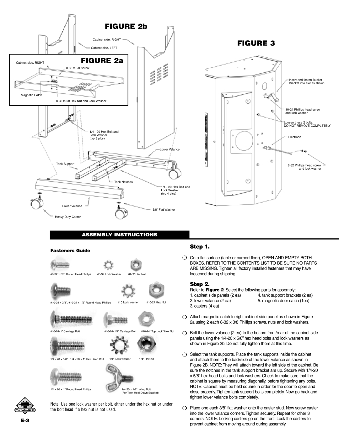
Refer to Figure 2. Select the following parts for assembly:
1. cabinet side panels (2 ea) | 4. tank support brackets (2 ea) |
2. lower valance (2 ea) | 5. magnetic door catch (1ea) |
3. casters (4 ea)
❍Attach magnetic catch to right cabinet side panel as shown in Figure 2a using 2 each
❍Bolt the lower valance (2 ea) to the bottom front/rear of the cabinet side panels using the
❍Select the tank supports. Place the tank supports inside the cabinet and attach them to the backside of the lower valance as shown in Figure 2B. NOTE: They will attach toward the left side of the cabinet. Be sure the notches in the tank support bracket are up. Secure with
❍Place one each 3/8” flat washer onto the caster stud. Now screw caster into the lower valance corners. Tighten securely. Repeat for other 3 corners. NOTE: Locking casters go on the front. Lock the casters to prevent cabinet from moving around during assembly.
