FIGURE 6
10
Cooking g Grid
Drip Pan |
|
FIGURE 8 | Drain Pipe |
10
and Lock Washer
Shelf Bracket
Utensil Hook
Drain Valve
Screws onto drain pipe Hand tighten only
Drip Bucket
Hangs on Bucket
Bracket
Condiment Tray | Cutaway to | |
show inside | ||
| ||
| detail only |
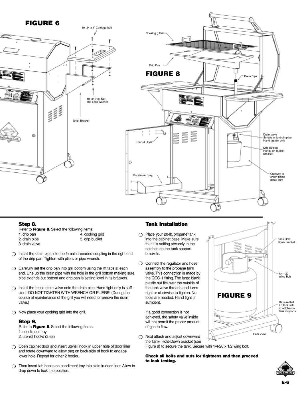
Step 8. | Tank Installation |
Refer to Figure 8. Select the following items:
1. drip pan | 4. cooking grid |
2. drain pipe | 5. drip bucket |
3. drain valve
❍Install the drain pipe into the female threaded coupling in the right end of the drip pan. Tighten with pliers or pipe wrench.
❍Carefully set the drip pan into grill bottom using the lift tabs at each end. Line up the drain pipe with the hole in the grill bottom making sure pipe extends out bottom and drip pan is setting level in its brackets.
❍Install the brass drain valve onto the drain pipe. Hand tight only is suffi- cient. DO NOT TIGHTEN WITH WRENCH OR PLIERS! (During the course of maintenance of the grill you will need to remove the drain valve.)
❍Now place your cooking grid into the grill.
Step 9.
Refer to Figure 8. Select the following items:
1.condiment tray
2.utensil hooks (3 ea)
❍Open cabinet door and insert utensil hook in upper hole of door liner and rotate downward to allow peg on back side of hook to engage lower hole. Repeat for other 2 hooks.
❍Then insert tab hooks on condiment tray into slots in door liner. Allow to drop down to lock into position.
❍ Place your |
|
into the cabinet base. Make sure | Tank Hold |
that it is setting securely in the | down Bracket |
| |
notches on the tank support |
|
brackets. |
|
❍ Connect the regulator and hose |
|
assembly to the propane tank |
|
valve. This connection is made by | 1/4 - 20 |
the | Wing Bolt |
| |
plastic nut fits over the outside of |
|
the tank valve threads and turns |
|
right or clockwise to tighten. No | FIGURE 9 |
tools are needed. Hand tight is | |
sufficient. | Be sure that |
| LP tank sets |
| in notches in |
If a good connection is not | tank supports |
achieved, the safety valve inside will not permit the proper amount of gas to flow.
Rear View
❍ Next attach and adjust downward the Tank-
Figure 9) to secure the tank. Secure with 1/4-20 x 1/2 wing bolt.
Check all bolts and nuts for tightness and then proceed to leak testing.