Other Features
Rain Off Mode
To stop the automatic watering cycles during winter, turn the dial to the Off position. The word “Off” will appear in the display. This means the automatic programs will not come on, but the programmed information is still retained in the memory. To reactivate the automatic schedule, turn the dial back to the Auto Run position.
NOTE: If a rain sensor has been connected, the stations set to rain sensor control, will be turned OFF automatically, when the sensor is wet.
Water Budgeting
The automatic station run times can be adjusted by percentage as the seasons change. This will save time and money as the run times can be adjusted quickly in spring, winter and autumn to reduce the amount of water used.
Ensure that the dial is in the Auto Run position and then press the back and next buttons simultaneously.
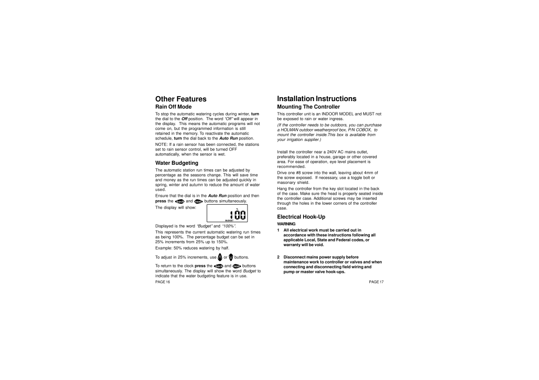
The display will show:
Displayed is the word “Budget” and “100%”.
This represents the current automatic watering run times as being 100%. The percentage budget can be set in 25% increments from 25% up to 150%.
Example: 50% reduces watering by half.
To adjust in 25% increments, use ![]() or
or ![]() buttons.
buttons.
To return to the clock press the back and next buttons simultaneously. The display will show the word Budget to indicate that the water budgeting feature is in use.
Installation Instructions
Mounting The Controller
This controller unit is an INDOOR MODEL and MUST not be exposed to rain or water ingress.
(If the controller needs to be outdoors, you can purchase a HOLMAN outdoor weatherproof box, P/N COBOX, to mount the controller inside.This box is available from your irrigation supplier.)
Install the controller near a 240V AC mains outlet, preferably located in a house, garage or other covered area. For ease of operation, eye level placement is recommended.
Drive one #8 screw into the wall, leaving about 4mm of the screw exposed. If necessary, use a toggle bolt or masonary shield.
Hang the controller from the key slot located in the back of the case. Make sure the head is properly seated inside the controller case. Additional screws may be inserted through the holes in the lower corners of the controller case.
Electrical Hook-Up
WARNING
1All electrical work must be carried out in accordance with these instructions following all applicable Local, State and Federal codes, or warranty will be void.
2Disconnect mains power supply before maintenance work to controller or valves and when connecting and disconnecting field wiring and pump or master valve
PAGE 16 | PAGE 17 |