ELECTRICAL
EXTENSION CORD CABLE SIZE
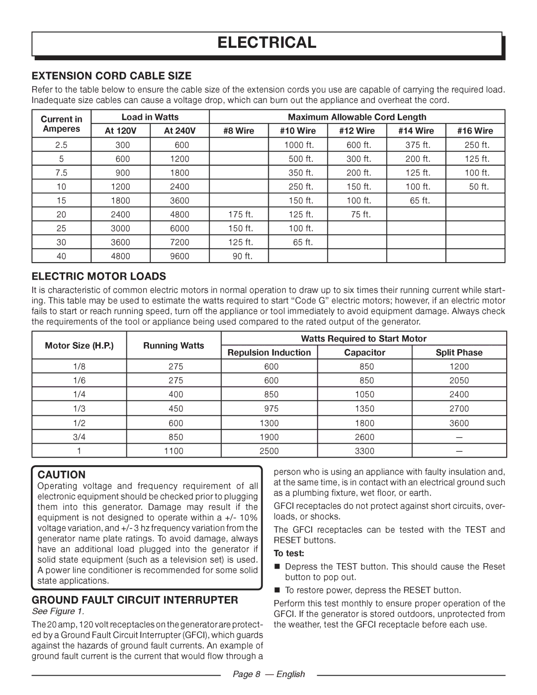
Refer to the table below to ensure the cable size of the extension cords you use are capable of carrying the required load. Inadequate size cables can cause a voltage drop, which can burn out the appliance and overheat the cord.
Current in | Load in Watts |
| Maximum Allowable Cord Length |
| |||
Amperes | At 120V | At 240V | #8 Wire | #10 Wire | #12 Wire | #14 Wire | #16 Wire |
|
|
|
|
|
|
|
|
2.5 | 300 | 600 |
| 1000 ft. | 600 ft. | 375 ft. | 250 ft. |
|
|
|
|
|
|
|
|
5 | 600 | 1200 |
| 500 ft. | 300 ft. | 200 ft. | 125 ft. |
|
|
|
|
|
|
|
|
7.5 | 900 | 1800 |
| 350 ft. | 200 ft. | 125 ft. | 100 ft. |
10 | 1200 | 2400 |
| 250 ft. | 150 ft. | 100 ft. | 50 ft. |
|
|
|
|
|
|
|
|
15 | 1800 | 3600 |
| 150 ft. | 100 ft. | 65 ft. |
|
|
|
|
|
|
|
|
|
20 | 2400 | 4800 | 175 ft. | 125 ft. | 75 ft. |
|
|
|
|
|
|
|
|
|
|
25 | 3000 | 6000 | 150 ft. | 100 ft. |
|
|
|
|
|
|
|
|
|
|
|
30 | 3600 | 7200 | 125 ft. | 65 ft. |
|
|
|
|
|
|
|
|
|
|
|
40 | 4800 | 9600 | 90 ft. |
|
|
|
|
|
|
|
|
|
|
|
|
ELECTRIC MOTOR LOADS
It is characteristic of common electric motors in normal operation to draw up to six times their running current while start- ing. This table may be used to estimate the watts required to start “Code G” electric motors; however, if an electric motor fails to start or reach running speed, turn off the appliance or tool immediately to avoid equipment damage. Always check the requirements of the tool or appliance being used compared to the rated output of the generator.
Motor Size (H.P.) | Running Watts | Watts Required to Start Motor |
| ||
|
|
|
| ||
Repulsion Induction | Capacitor |
| Split Phase | ||
|
|
| |||
|
|
|
|
|
|
1/8 | 275 | 600 | 850 |
| 1200 |
|
|
|
|
|
|
1/6 | 275 | 600 | 850 |
| 2050 |
|
|
|
|
|
|
1/4 | 400 | 850 | 1050 |
| 2400 |
|
|
|
|
|
|
1/3 | 450 | 975 | 1350 |
| 2700 |
|
|
|
|
|
|
1/2 | 600 | 1300 | 1800 |
| 3600 |
|
|
|
|
|
|
3/4 | 850 | 1900 | 2600 |
| — |
|
|
|
|
|
|
1 | 1100 | 2500 | 3300 |
| — |
|
|
|
|
|
|
CAUTION
Operating voltage and frequency requirement of all electronic equipment should be checked prior to plugging them into this generator. Damage may result if the equipment is not designed to operate within a +/- 10% voltage variation, and +/- 3 hz frequency variation from the generator name plate ratings. To avoid damage, always have an additional load plugged into the generator if solid state equipment (such as a television set) is used. A power line conditioner is recommended for some solid state applications.
GROUND FAULT CIRCUIT INTERRUPTER
See Figure 1.
The 20 amp, 120 volt receptacles on the generator are protect- ed by a Ground Fault Circuit Interrupter (GFCI), which guards against the hazards of ground fault currents. An example of ground fault current is the current that would flow through a
person who is using an appliance with faulty insulation and, at the same time, is in contact with an electrical ground such as a plumbing fixture, wet floor, or earth.
GFCI receptacles do not protect against short circuits, over- loads, or shocks.
The GFCI receptacles can be tested with the TEST and RESET buttons.
To test:
Depress the TEST button. This should cause the Reset button to pop out.
To restore power, depress the RESET button.
Perform this test monthly to ensure proper operation of the GFCI. If the generator is stored outdoors, unprotected from the weather, test the GFCI receptacle before each use.
Page 8 — English