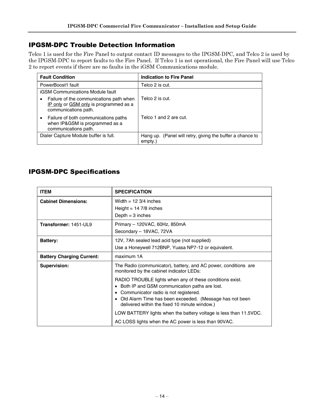
IPGSM-DPC specifications
The Honeywell IPGSM-DPC is an advanced communication device designed for alarm systems, providing a reliable and robust connection to monitoring services. This dual-path communicator integrates both internet and cellular technologies, ensuring that security alarm signals are transmitted without interruption. Its ability to utilize both pathways enhances the reliability of the alarm signals, especially in situations where one mode of communication might fail.One of the standout features of the IPGSM-DPC is its compatibility with Honeywell's Total Connect service, which allows users to remotely monitor and manage their security systems via a smartphone, tablet, or computer. This feature provides real-time alerts and updates, giving users peace of mind and control over their security environment. With Total Connect, users can also receive notifications for certain events like alarm triggers or system status changes.
The IPGSM-DPC is built with the latest in wireless communication technology. It operates on the LTE (Long-Term Evolution) network, which ensures fast data transmission speeds and a wider coverage area. Additionally, the device supports multiple communication formats, making it flexible and adaptable to various alarm panel configurations. This versatility allows for easy integration into existing security systems without the need for extensive rewiring or hardware replacements.
Moreover, the Honeywell IPGSM-DPC features a built-in backup battery, ensuring continued operation even in the event of a power outage. This added layer of security is crucial for maintaining protection during emergencies. The device is designed with user-friendly installation in mind, allowing both professionals and DIY users to set it up quickly and efficiently.
Another notable characteristic is its robust encryption methods, which protect data during transmission. This ensures that sensitive information related to security alarms remains secure from potential cyber threats. The IPGSM-DPC is also equipped with diagnostic features, allowing users to monitor the health and performance of their communication paths, helping to preemptively address any connectivity issues.
In summary, the Honeywell IPGSM-DPC is a state-of-the-art dual-path communicator that enhances the reliability and security of alarm systems. With its integration capabilities, robust cellular technology, user-friendly installation process, and advanced security features, it stands out as an essential component for modern security solutions. Whether used in residential or commercial applications, it offers peace of mind and advanced control over alarm systems.