Wiring Diagram

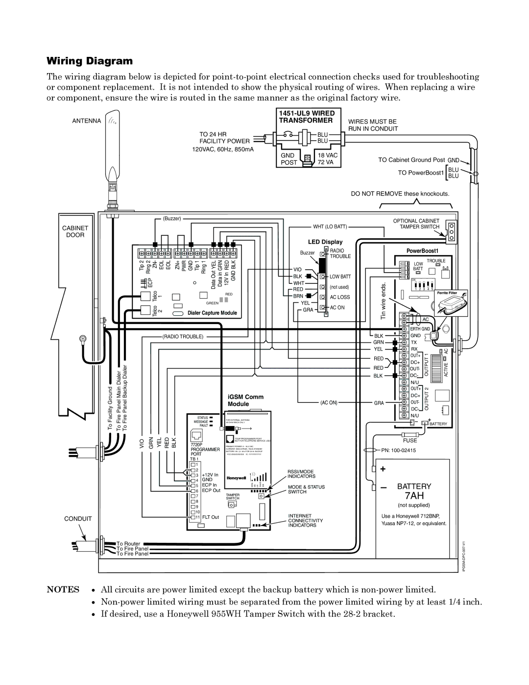
The wiring diagram below is depicted for point-to-point electrical connection checks used for troubleshooting or component replacement. It is not intended to show the physical routing of wires. When replacing a wire or component, ensure the wire is routed in the same manner as the original factory wire.

ANTENNA

TO 24 HR

FACILITY POWER 120VAC, 60Hz, 850mA

1451-UL9 WIRED

TRANSFORMER WIRES MUST BE

RUN IN CONDUIT

BLU

BLU

GND


18 VAC

TO Cabinet Ground Post GND

POST


72 VA


TO PowerBoost1 BLUBLU

DO NOT REMOVE these knockouts.

CABINET

DOOR


(Buzzer)


Ring2


YEL

RED

Tip2

ECP ZN-

EOL EOL

ZN+

WPR

GND Tip1 Ring1

Data Out DataGRNin

12V In GNDBLK


Telco

1


RED


Telco


GREEN


2


Dialer Capture Module


(RADIO TROUBLE)


WHT (LO BATT)

LED Display

Buzzer

RADIO

TROUBLE


VIO

BLK LOW BATT

WHT

RED (not used)

BRN AC LOSS

YEL

GRA AC ON


OPTIONAL CABINET


TAMPER SWITCH


PowerBoost1


LOW


TROUBLE


BATT


ends.wireTin

ON


1

2

3

4

5


AC


ERTH GND


BLK

GND


GRN

TX


YEL

RX


AC

RED

OUT+

1


DC+


Dialer

up Dialer


FacilityGround

PanelFire Main

PanelFire Back


MESSAGE

iGSM Comm

(AC ON)


50 OHM MMCX ONLY


Module


STATUS

FOR EXTERNAL ANTENNA


To

To

To


FAULT


VIO

GRN

YEL

RED

BLK


7720P PROGRAMMER PORT


NOT FOR TELEPHONE SERVICE USE!


7720P

PRIMARY POWER: 9 - 16.5 VAC


PROGRAMMER

BATTERY: 8V. 3.1 AHr FOR 24 Hr BACKUP


PORT


CURRENT: 900mA PEAK, 70mA STANDBY


FCC:XXXXXXXXXX IC: YYYYYYYYYY


TB 1


1


2

+12V In


RSSI/MODE


3


INDICATORS


4

GND


GPRS M1 M0 RSSI


5

ECP In

IBS

MODE & STATUS


6

ECP Out


TAMPER


SWITCH


7


8


SWITCH


9


10


INTERNET

CONDUIT


11

FLT Out


CONNECTIVITY


INDICATORS

To Router

To Fire Panel

To Fire Panel

RED

OUT-

OUTPUT

ACTIVE

BLK

DC-


N/U


OUT+

2


DC+

OUTPUT


GRA

OUT-


DC-


N/U


BATTERY

FUSE

PN: 100-02415

+

BATTERY

7AH

(not supplied)

Use a Honeywell 712BNP,

Yuasa NP7-12, or equivalent.

IPGSM-DPC-007-V1

NOTES All circuits are power limited except the backup battery which is non-power limited.

Non-power limited wiring must be separated from the power limited wiring by at least 1/4 inch.

If desired, use a Honeywell 955WH Tamper Switch with the 28-2 bracket.

Page 23
Image 23
Honeywell IPGSM-DPC manual Battery

IPGSM-DPC specifications

The Honeywell IPGSM-DPC is an advanced communication device designed for alarm systems, providing a reliable and robust connection to monitoring services. This dual-path communicator integrates both internet and cellular technologies, ensuring that security alarm signals are transmitted without interruption. Its ability to utilize both pathways enhances the reliability of the alarm signals, especially in situations where one mode of communication might fail.

One of the standout features of the IPGSM-DPC is its compatibility with Honeywell's Total Connect service, which allows users to remotely monitor and manage their security systems via a smartphone, tablet, or computer. This feature provides real-time alerts and updates, giving users peace of mind and control over their security environment. With Total Connect, users can also receive notifications for certain events like alarm triggers or system status changes.

The IPGSM-DPC is built with the latest in wireless communication technology. It operates on the LTE (Long-Term Evolution) network, which ensures fast data transmission speeds and a wider coverage area. Additionally, the device supports multiple communication formats, making it flexible and adaptable to various alarm panel configurations. This versatility allows for easy integration into existing security systems without the need for extensive rewiring or hardware replacements.

Moreover, the Honeywell IPGSM-DPC features a built-in backup battery, ensuring continued operation even in the event of a power outage. This added layer of security is crucial for maintaining protection during emergencies. The device is designed with user-friendly installation in mind, allowing both professionals and DIY users to set it up quickly and efficiently.

Another notable characteristic is its robust encryption methods, which protect data during transmission. This ensures that sensitive information related to security alarms remains secure from potential cyber threats. The IPGSM-DPC is also equipped with diagnostic features, allowing users to monitor the health and performance of their communication paths, helping to preemptively address any connectivity issues.

In summary, the Honeywell IPGSM-DPC is a state-of-the-art dual-path communicator that enhances the reliability and security of alarm systems. With its integration capabilities, robust cellular technology, user-friendly installation process, and advanced security features, it stands out as an essential component for modern security solutions. Whether used in residential or commercial applications, it offers peace of mind and advanced control over alarm systems.