INSTALLATION | ||
|
|
|
FUEL CAP
Remove the plastic cap covering from the Fuel Tank Filler neck and install the Fuel Cap.
ENGINE COOLING SYSTEM
The Deutz engine is air cooled by a belt driven axial blower. The oil cooler and engine cooling fins should be blown out with compressed air or steam to maintain proper cooling (See the engine Owners Manual for pro- cedures and frequency).
BATTERY CONNECTION
WARNING: Use caution as the electrolyte is a strong acid that can burn skin and damage eyes.
Remove and discard the insulating cap from the nega- tive battery terminal. Attach and tighten negative bat- tery cable terminal.
NOTE: This machine is furnished with a wet charged battery; if unused for several months, the battery may require a booster charge. Be careful to charge the battery with the correct polar- ity. Make sure that the battery is level while charging.
MUFFLER OUTLET PIPE
Remove the plastic plug covering the muffler outlet tube. Using the clamp provided secure the outlet pipe to the outlet tube with the pipe positioned such that it will direct the exhaust in the desired direction.
SPARK ARRESTER
Some federal, state or local laws may require that gasoline or diesel engines be equipped with exhaust spark arresters when they are operated in certain loca- tions where unarrested sparks may present a fire haz- ard. The standard muffler included with this welder does not qualify as a spark arrester. When required by local regulations, a suitable spark arrester, such as the
![]() CAUTION
CAUTION
An incorrect arrester may lead to damage to the engine or adversely affect performance.
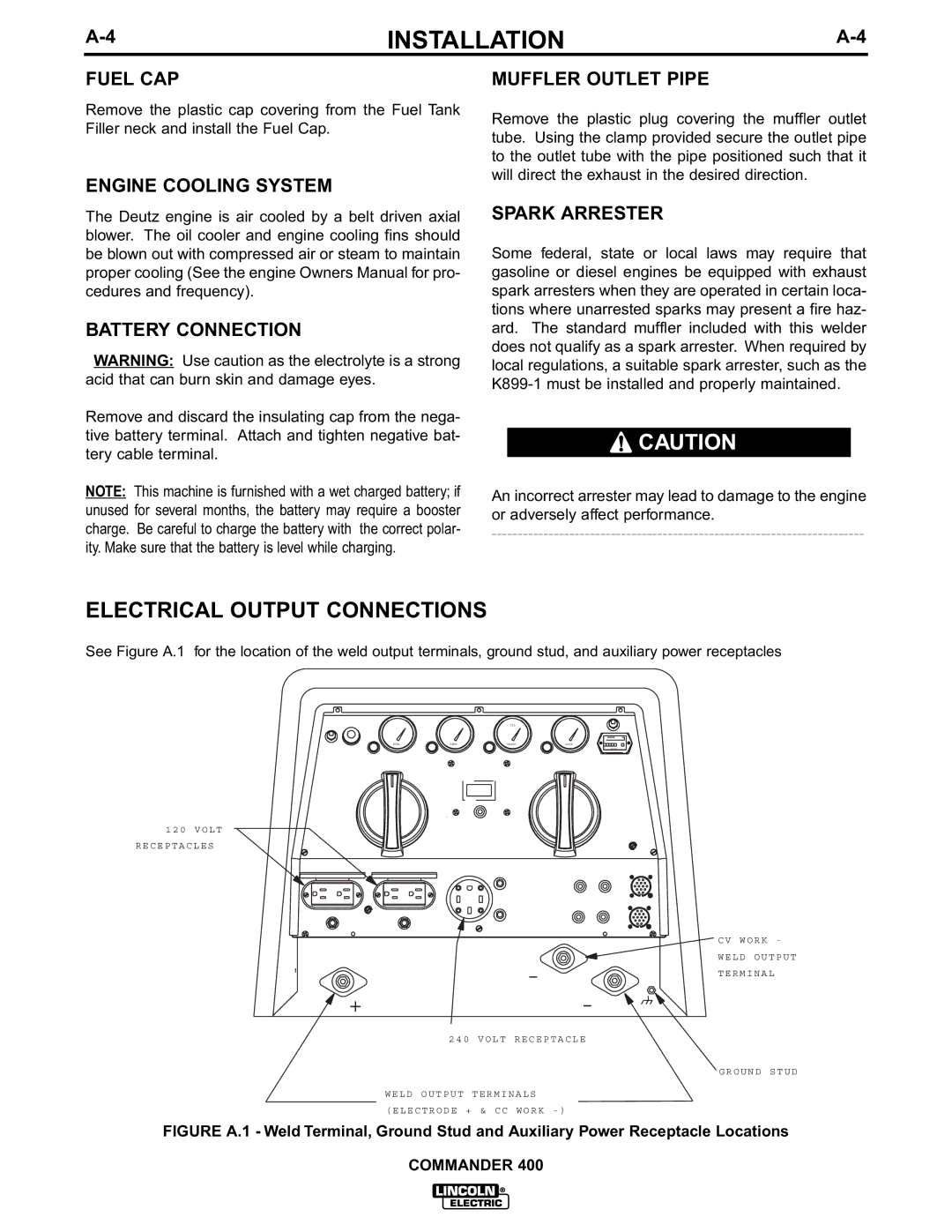
ELECTRICAL OUTPUT CONNECTIONS
See Figure A.1 for the location of the weld output terminals, ground stud, and auxiliary power receptacles
OIL
FUEL | TEMP | PRESS | AMPS |
1 2 0 V O L T
R E C E P T A C L E S
0 | 0 | 0 | 0 | 0 | 0 |
H O U R S
C V W O R K -
| - |
+ | - |
| 2 4 0 V O L T R E C E P T A C L E |
| W E L D O U T P U T T E R M I N A L S |
| ( E L E C T R O D E + & C C W O R K - ) |
W E L D O U T P U T T E R M I N A L
G R O U N D S T U D
FIGURE A.1 - Weld Terminal, Ground Stud and Auxiliary Power Receptacle Locations
COMMANDER 400