OPERATION | ||
|
|
|
AUXILIARY POWER OPERATION
Start the engine and set the IDLER control switch to the desired operating mode. Full power is available regardless of the welding control settings, if no welding current is being drawn..
The auxiliary power of the Commander consists of two- 120VAC
The auxiliary power capacity is 10,000 watts of 60 Hz, single phase power. The auxiliary power capacity rat- ing in watts is equivalent to
NOTE: The 240V receptacle has two 120V outlets of different phases and cannot be paralleled.
The auxiliary power receptacles should only be used with three wire grounded type plugs or approved dou- ble insulated tools with two wire plugs.
The current rating of any plug used with the system must be at least equal to the current capacity of the associated receptacle.
SIMULTANEOUS WELDING AND AUXIL- IARY POWER LOADS
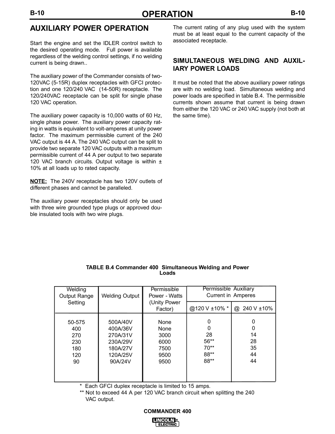
It must be noted that the above auxiliary power ratings are with no welding load. Simultaneous welding and power loads are specified in table B.4. The permissible currents shown assume that current is being drawn from either the 120 VAC or 240 VAC supply (not both at the same time).
TABLE B.4 Commander 400 Simultaneous Welding and Power
Loads
Welding
Output Range
Setting
Welding Output
Permissible
Power - Watts
(Unity Power
Permissible Auxiliary Current in Amperes
400
270
230
180
120
90
500A/40V
400A/36V
270A/31V
230A/29V
180A/27V
120A/25V
90A/24V
Factor)
None None 3000 6000 7500 9500 9500
@120 V ±10% *
0
0
28
56**
70**
88**
88**
@ 240 V ±10%
0
0
14
28
35
44
44
*Each GFCI duplex receptacle is limited to 15 amps.
**Not to exceed 44 A per 120 VAC branch circuit when splitting the 240 VAC output.
COMMANDER 400