Manuals
/
Honeywell
/
Household Appliance
/
Home Security System
Honeywell
PRO-2200
installation manual
Description, Set Up, Jumper, Setting, Default, Selected
Models:
PRO-2200
1
9
20
20
Download
20 pages
9.1 Kb
6
7
8
9
10
11
12
13
Page 9
Image 9
Page 8
Page 10
Page 9
Image 9
Page 8
Page 10
Contents
PRO-2200 Two Reader Module Installation Manual
Part Number PRO22R2
A division of Northern Computers, Inc
Page
Contents
Fire Safety and Liability Notice
Warnings and Cautions
Page
Unpacking Procedure
Disclaimer
Product Liability Mutual Indemnification
Limited Warranty
Shipping Instructions
To ship equipment back to Engineered Systems
Confidentiality
Installation Guide
PRO-2200Two Reader Module PRO22R2
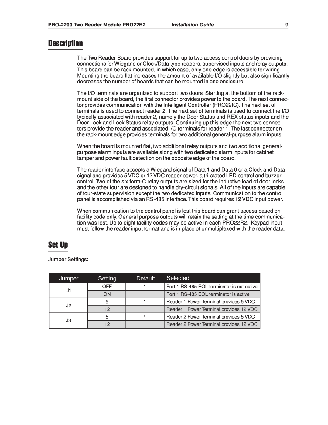
Description
Set Up
Setting
Default
= Default
Dipswitch Settings
Installation Guide
PRO-2200Two Reader Module PRO22R2
LED Operation
Power
Communications
MODE
Reader Wiring
For Wiring to an RS-485port
For wiring to a reader port
Control Output Wiring
Alarm Contact Wiring
Single Wire Reader LED Control Configuration
LED Output
Suggested Installation Sequence
Mounting Options
See diagram to follow
Primary power 12VDC±10% 400mA Relay contacts
Specification
Inputs
Reader interface
Installation Guide
Wiring Diagram for Connectors 1 through
Power VDC
Separate - Power VDC Supply +
Wiring Diagram for Connectors 6 through
Installation Guide
PRO-2200Two Reader Module PRO22R2
PRO-2200Two Reader Module PRO22R2
Installation Guide
Page
2700 Blankenbaker Pkwy, Suite Louisville, KY
Honeywell Security & Data Collection
Top
Page
Image
Contents