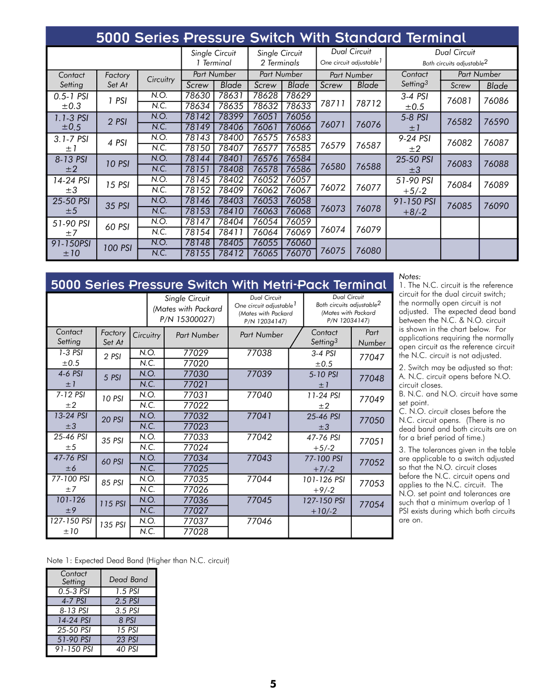
5000 Series Pressure Switch With Standard Terminal
|
|
| Single Circuit | Single Circuit | Dual Circuit |
| Dual Circuit |
| |||||
|
|
| 1 Terminal | 2 Terminals | One circuit adjustable1 | Both circuits adjustable2 | |||||||
Contact | Factory | Circuitry | Part Number | Part Number | Part Number | Contact |
|
| Part Number | ||||
Setting | Set At | Screw | Blade | Screw | Blade | Screw | Blade | Setting3 |
|
| Screw | Blade | |
|
|
| |||||||||||
1 PSI | N.O. | 78630 | 78631 | 78628 | 78629 | 78711 | 78712 |
|
| 76081 | 76086 | ||
±0.3 | N.C. | 78634 | 78635 | 78632 | 78633 | ±0.5 |
|
| |||||
|
|
|
|
| |||||||||
2 PSI | N.O. | 78142 | 78399 | 76051 | 76056 | 76071 | 76076 |
|
| 76582 | 76590 | ||
±0.5 | N.C. | 78149 | 78406 | 76061 | 76066 | ±1 |
|
| |||||
|
|
|
|
| |||||||||
4 PSI | N.O. | 78143 | 78400 | 76575 | 76583 | 76579 | 76587 |
|
| 76082 | 76087 | ||
±1 | N.C. | 78150 | 78407 | 76577 | 76585 | ±2 |
|
| |||||
|
|
|
|
| |||||||||
10 PSI | N.O. | 78144 | 78401 | 76576 | 76584 | 76580 | 76588 |
|
| 76083 | 76088 | ||
±2 | N.C. | 78151 | 78408 | 76578 | 76586 | ±3 |
|
| |||||
|
|
|
|
| |||||||||
15 PSI | N.O. | 78145 | 78402 | 76052 | 76057 | 76072 | 76077 |
|
| 76084 | 76089 | ||
±3 | N.C. | 78152 | 78409 | 76062 | 76067 |
|
|
| |||||
|
|
|
|
| |||||||||
35 PSI | N.O. | 78146 | 78403 | 76053 | 76058 | 76073 | 76078 | 76085 | 76090 | ||||
±5 | N.C. | 78153 | 78410 | 76063 | 76068 |
|
|
| |||||
|
|
|
|
| |||||||||
60 PSI | N.O. | 78147 | 78404 | 76054 | 76059 | 76074 | 76079 |
|
|
|
|
| |
±7 | N.C. | 78154 | 78411 | 76064 | 76069 |
|
|
|
|
| |||
|
|
|
|
|
| ||||||||
100 PSI | N.O. | 78148 | 78405 | 76055 | 76060 | 76075 | 76080 |
|
|
|
|
| |
±10 | N.C. | 78155 | 78412 | 76065 | 76070 |
|
|
|
|
| |||
|
|
|
|
|
| ||||||||
5000 Series Pressure Switch With Metri-Pack Terminal
|
|
|
|
|
|
| Single Circuit |
| Dual Circuit | Dual Circuit | ||
|
|
|
|
| (Mates with Packard |
| One circuit adjustable1 | Both circuits adjustable2 | ||||
|
|
|
|
|
| (Mates with Packard | (Mates with Packard | |||||
|
|
|
|
|
| P/N 15300027) |
| |||||
|
|
|
|
|
|
| P/N 12034147) | P/N 12034147) | ||||
|
|
|
|
|
|
|
|
|
|
|
|
|
Contact |
| Factory | Circuitry | Part Number |
| Part Number | Contact | Part | ||||
Setting |
| Set At |
|
|
|
|
|
|
| Setting3 | Number | |
| 2 PSI |
| N.O. | 77029 |
| 77038 |
| 77047 | ||||
±0.5 |
|
| N.C. | 77020 |
|
|
| ±0.5 | ||||
|
|
|
|
|
|
| ||||||
| 5 PSI | N.O. | 77030 |
| 77039 |
| 77048 | |||||
±1 |
| N.C. | 77021 |
|
|
| ±1 | |||||
|
|
|
|
|
|
| ||||||
| 10 PSI | N.O. | 77031 |
| 77040 |
| 77049 | |||||
±2 |
| N.C. | 77022 |
|
|
| ±2 | |||||
|
|
|
|
|
|
| ||||||
| 20 PSI | N.O. | 77032 |
| 77041 |
| 77050 | |||||
±3 |
| N.C. | 77023 |
|
|
| ±3 | |||||
|
|
|
|
|
|
| ||||||
| 35 PSI | N.O. | 77033 |
| 77042 |
| 77051 | |||||
±5 |
| N.C. | 77024 |
|
|
| ||||||
|
|
|
|
|
|
| ||||||
| 60 PSI | N.O. | 77034 |
| 77043 |
| 77052 | |||||
±6 |
| N.C. | 77025 |
|
|
| ||||||
|
|
|
|
|
|
| ||||||
| 85 PSI | N.O. | 77035 |
| 77044 |
| 77053 | |||||
±7 |
| N.C. | 77026 |
|
|
| ||||||
|
|
|
|
|
|
| ||||||
115 PSI | N.O. | 77036 |
| 77045 |
| 77054 | ||||||
±9 | N.C. | 77027 |
|
|
| |||||||
|
|
|
|
|
|
| ||||||
135 PSI | N.O. | 77037 |
| 77046 |
|
|
| |||||
±10 | N.C. | 77028 |
|
|
|
|
| |||||
|
|
|
|
|
|
|
| |||||
Note 1: Expected Dead Band (Higher than N.C. circuit) |
|
|
|
| ||||||||
|
|
|
|
|
|
|
|
|
|
|
|
|
Contact |
| Dead Band |
|
|
|
|
|
|
| |||
Setting |
|
|
|
|
|
|
|
| ||||
| 1.5 PSI |
|
|
|
|
|
|
| ||||
| 2.5 PSI |
|
|
|
|
|
|
| ||||
| 3.5 PSI |
|
|
|
|
|
|
| ||||
| 8 PSI |
|
|
|
|
|
|
| ||||
|
| 15 PSI |
|
|
|
|
|
|
| |||
|
| 23 PSI |
|
|
|
|
|
|
| |||
|
| 40 PSI |
|
|
|
|
|
|
| |||
Notes:
1.The N.C. circuit is the reference circuit for the dual circuit switch; the normally open circuit is not adjusted. The expected dead band between the N.C. & N.O. circuit is shown in the chart below. For applications requiring the normally open circuit as the reference circuit the N.C. circuit is not adjusted.
2.Switch may be adjusted so that: A. N.C. circuit opens before N.O. circuit closes.
B. N.C. and N.O. circuit have same set point.
C. N.O. circuit closes before the N.C. circuit opens. (There is no dead band and both circuits are on for a brief period of time.)
3.The tolerances given in the table are applicable to a switch adjusted so that the N.O. circuit closes before the N.C. circuit opens and applies to the N.C. circuit. The N.O. set point and tolerances are such that a minimum overlap of 1 PSI exists during which both circuits are on.
5