8162, TH114-A-240D specifications
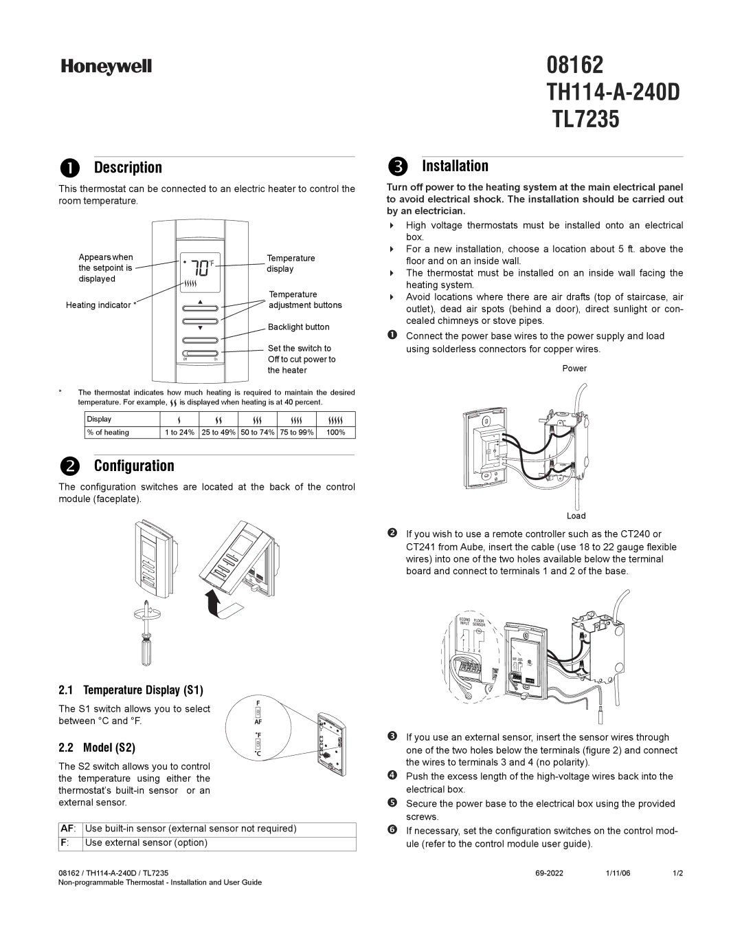
The Honeywell 8162, TH114-A-240D is a sophisticated and efficient thermostat engineered to deliver precise temperature control and enhance comfort in residential and commercial settings. This device stands out in the HVAC market for its user-friendly features and advanced technologies, making it a preferred choice among homeowners and facility managers alike.At the core of the Honeywell 8162's functionality is its versatile programming capacity. The thermostat enables users to set specific temperature schedules for different times of the day, promoting energy savings and ensuring optimal comfort. Its 7-day programming capability allows for customized heating or cooling schedules for each day of the week, catering to varying lifestyle demands.
One of the most notable features of the TH114-A-240D is its intuitive digital display, which provides clear visibility of the current temperature and settings. The straightforward interface makes it easy for users to navigate through options and make adjustments without confusion. The large, backlit screen ensures readability in any lighting condition, adding further convenience.
Moreover, the Honeywell 8162 employs advanced technology, including an adaptive intelligent recovery feature. This technology allows the thermostat to learn how long it takes to reach a certain temperature and begins the heating or cooling process ahead of time. As a result, the desired comfort level is achieved promptly, while also minimizing energy consumption.
The TH114-A-240D is compatible with a variety of heating and cooling systems, including both gas and electric setups, making it an adaptable choice for many different applications. Additionally, the device supports a wide range of voltages, further enhancing its versatility.
A significant characteristic of the Honeywell 8162 is its energy efficiency. It is designed with energy-saving settings that can noticeably reduce heating and cooling costs over time. The thermostat can also alert users to filter replacement needs, contributing to better air quality and system performance.
In summary, the Honeywell 8162 TH114-A-240D thermostat brings together advanced programming features, user-friendly design, and energy-saving technologies in one reliable device. It offers a perfect blend of comfort, efficiency, and control, making it an excellent choice for anyone looking to enhance their indoor climate management.

