Table of gas consumption |
|
|
|
| 1W = 0,860 kcal/h |
| X dimension according |
| ||||||||
|
|
|
|
|
|
|
|
|
|
|
|
| to Gas type |
| ||
| G20/G25 | G30 | G20 20mbar |
|
|
|
| G25 |
|
| G20 |
| G30 | G25 |
| G31 |
| G31 | G30 29mbar |
|
|
|
| 25mbar |
|
|
|
| |||||
|
| G31 37mbar |
|
|
|
|
|
|
|
|
|
|
|
| ||
|
|
|
|
|
|
|
|
|
|
|
|
|
|
|
| |
Working | Ø gas jet | Ø gas jet | STD. Dim | l/h | g/h | g/h |
| Qn | l/h | min.Dim | reg. |
| reg. | reg. |
| reg. |
burner | 1/100 mm | 1/100 mm | kW | G20 | G30 | G31 |
| kW | G25 | kW | air |
| air | air |
| air |
|
|
|
|
|
|
|
|
|
|
|
|
|
|
|
|
|
large | 120 | 80 | 2,65 | 252 | 193 | 189 |
| 2,5 | 277 | 0,65 | 4 mm |
| 2 mm | 4 mm |
| 5 mm |
|
|
|
|
|
|
|
|
|
|
|
|
|
|
|
|
|
medium | 93 | 61 | 1,5 | 143 | 109 | 107 |
| 1,45 | 161 | 0,38 | 2 mm |
| 5 mm | 2 mm |
| 7 mm |
|
|
|
|
|
|
|
|
|
|
|
|
|
|
|
|
|
maxi | 2x94 | 2x65 | 3,3 | 314 | 238 | 236 |
| 3,1 | 343 | 0,9 | 15 mm |
| 0 mm | 15 mm |
| 15 mm |
|
|
|
|
|
|
|
|
|
|
|
|
|
|
|
|
|
double ring | 2x94 | 2x65 | 3,3 | 314 | 238 | 236 |
| 3,1 | 343 | 0,9 | 13 mm |
| 0 mm | 13 mm |
| 15 mm |
|
|
|
|
|
|
|
|
|
|
|
|
|
|
|
|
|
fish | 2x94 | 2x65 | 3,3 | 314 | 238 | 236 |
| 3,1 | 343 | 0,9 | 15 mm |
| 0 mm | 15 mm |
| 15 mm |
|
|
|
|
|
|
|
|
|
|
|
|
|
|
|
|
|
SETTING OF THE GAS BURNERS
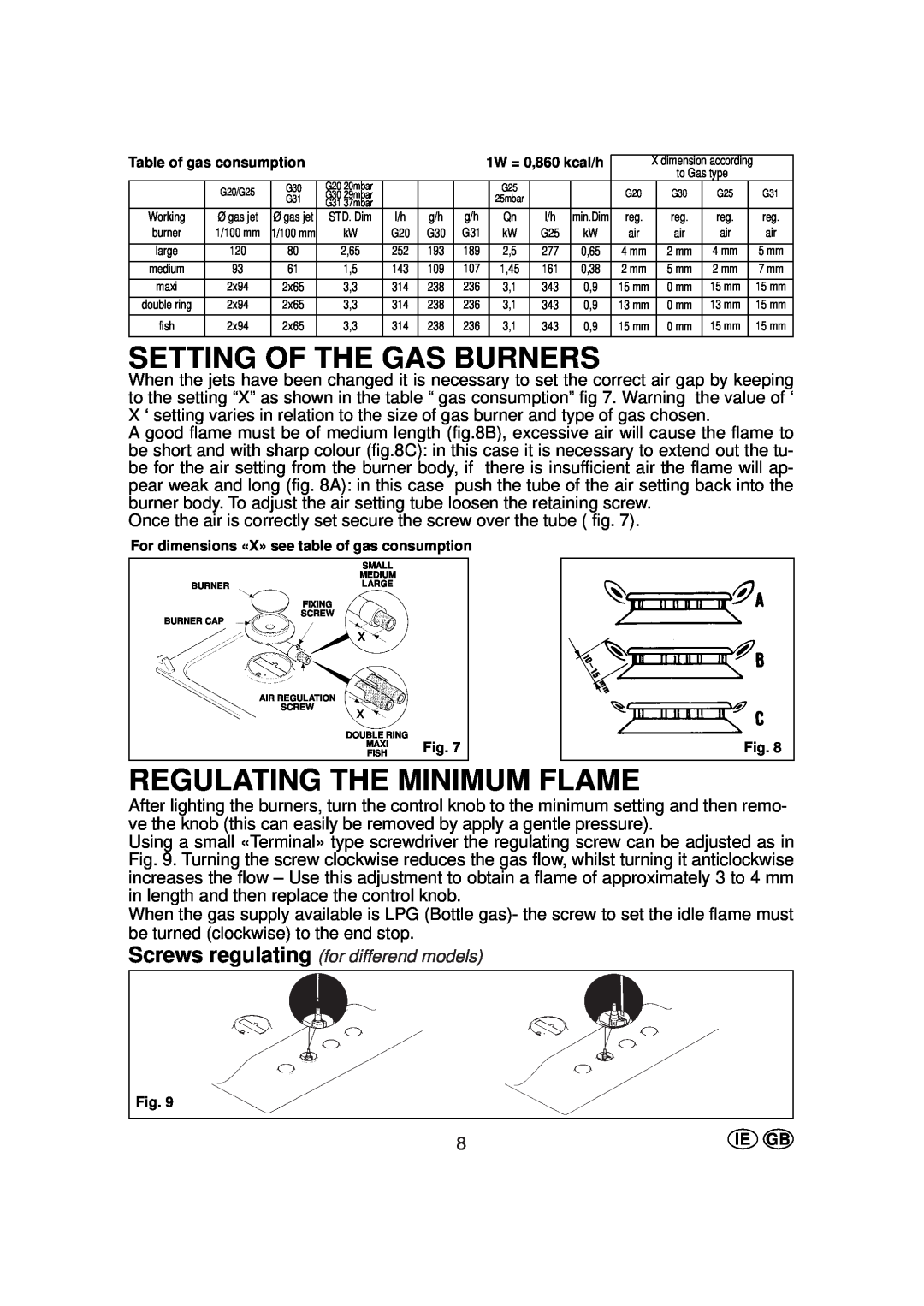
When the jets have been changed it is necessary to set the correct air gap by keeping to the setting “X” as shown in the table “ gas consumption” fig 7. Warning the value of ‘ X ‘ setting varies in relation to the size of gas burner and type of gas chosen.
A good flame must be of medium length (fig.8B), excessive air will cause the flame to be short and with sharp colour (fig.8C): in this case it is necessary to extend out the tu- be for the air setting from the burner body, if there is insufficient air the flame will ap- pear weak and long (fig. 8A): in this case push the tube of the air setting back into the burner body. To adjust the air setting tube loosen the retaining screw.
Once the air is correctly set secure the screw over the tube ( fig. 7).
For dimensions «X» see table of gas consumption
| SMALL |
|
| MEDIUM |
|
BURNER | LARGE |
|
| FIXING |
|
BURNER CAP | SCREW |
|
|
| |
| AIR REGULATION |
|
| SCREW |
|
| DOUBLE RING |
|
| MAXI | Fig. 7 |
| FISH |
Fig. 8
REGULATING THE MINIMUM FLAME
After lighting the burners, turn the control knob to the minimum setting and then remo- ve the knob (this can easily be removed by apply a gentle pressure).
Using a small «Terminal» type screwdriver the regulating screw can be adjusted as in Fig. 9. Turning the screw clockwise reduces the gas flow, whilst turning it anticlockwise increases the flow – Use this adjustment to obtain a flame of approximately 3 to 4 mm in length and then replace the control knob.
When the gas supply available is LPG (Bottle gas)- the screw to set the idle flame must be turned (clockwise) to the end stop.
Screws regulating (for differend models)
Fig. 9
8 | IE GB |