INTRODUCTION
A S S E M B LY STEP 5 - A (CST3 . 5 model)
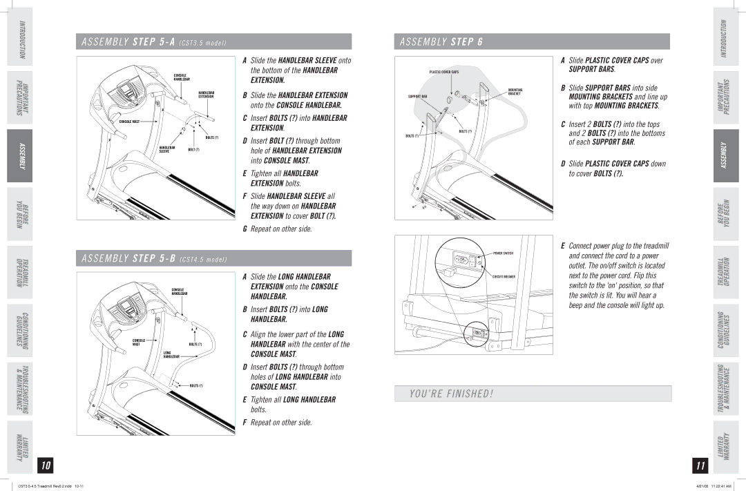
A S S E M B LY STEP 6
INTRODUCTION
IMPORTANT PRECAUTIONS
ASSEMBLY
BEFORE YOU BEGIN
�������
���������
���������
���������
������������ ![]()
���������
��������� ��������
������
ASlide the HANDLEBAR SLEEVE onto the bottom of the HANDLEBAR EXTENSION.
BSlide the HANDLEBAR EXTENSION onto the CONSOLE HANDLEBAR.
CInsert BOLTS (?) into HANDLEBAR EXTENSION.
DInsert BOLT (?) through bottom hole of HANDLEBAR EXTENSION into CONSOLE MAST.
ETighten all HANDLEBAR EXTENSION bolts.
FSlide HANDLEBAR SLEEVE all the way down on HANDLEBAR EXTENSION to cover BOLT (?).
GRepeat on other side.
| ������������������ |
| �������� |
����������� | ������� |
|
���������
���������
ASlide PLASTIC COVER CAPS over
SUPPORT BARS.
BSlide SUPPORT BARS into side MOUNTING BRACKETS and line up with top MOUNTING BRACKETS.
CInsert 2 BOLTS (?) into the tops and 2 BOLTS (?) into the bottoms of each SUPPORT BAR.
DSlide PLASTIC COVER CAPS down to cover BOLTS (?).
IMPORTANT PRECAUTIONS
ASSEMBLY
BEFORE YOU BEGIN
E Connect power plug to the treadmill |
TREADMILL CONDITIONING TROUBLESHOOTING LIMITED
OPERATION GUIDELINES & MAINTENANCE WARRANTY
10
A S S E M B LY STEP 5 - B (CST4 . 5 model)
| A | Slide the LONG HANDLEBAR | |
| ������� | EXTENSION onto the CONSOLE | |
| ��������� | HANDLEBAR. | |
|
| ||
| B | Insert BOLTS (?) into LONG | |
|
| HANDLEBAR. | |
������� | C Align the lower part of the LONG | ||
| HANDLEBAR with the center of the | ||
���� | ��������� | ||
CONSOLE MAST. | |||
| ��������� | ||
| ���� |
| |
| D | Insert BOLTS (?) through bottom | |
|
| holes of LONG HANDLEBAR into | |
| ��������� | CONSOLE MAST. | |
|
| ||
| E | Tighten all LONG HANDLEBAR | |
|
| bolts. | |
| F | Repeat on other side. | |
POWER SWITCH | and connect the cord to a power |
| |
| outlet. The on/off switch is located |
CIRCUIT BREAKER | next to the power cord. Flip this |
| switch to the 'on' position, so that |
| the switch is lit. You will hear a |
| beep and the console will light up. |
YOU’RE FINISHED!
11
LIMITED TROUBLESHOOTING CONDITIONING TREADMILL WARRANTY & MAINTENANCE GUIDELINES OPERATION
4/21/05 11:22:41 AM |