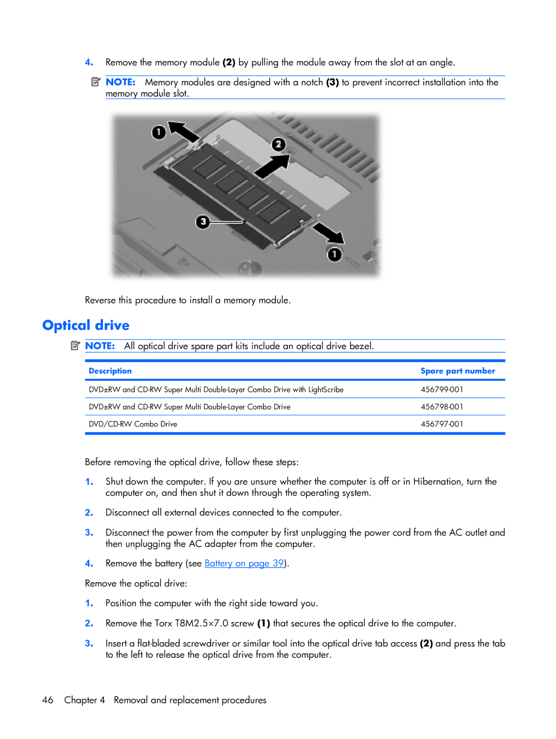
4. Remove the memory module (2) by pulling the module away from the slot at an angle.
![]() NOTE: Memory modules are designed with a notch (3) to prevent incorrect installation into the memory module slot.
NOTE: Memory modules are designed with a notch (3) to prevent incorrect installation into the memory module slot.
Reverse this procedure to install a memory module.
Optical drive
![]() NOTE: All optical drive spare part kits include an optical drive bezel.
NOTE: All optical drive spare part kits include an optical drive bezel.
Description | Spare part number |
|
|
DVD±RW and | |
|
|
DVD±RW and | |
|
|
|
|
Before removing the optical drive, follow these steps:
1. Shut down the computer. If you are unsure whether the computer is off or in Hibernation, turn the computer on, and then shut it down through the operating system.
2. Disconnect all external devices connected to the computer.
3. Disconnect the power from the computer by first unplugging the power cord from the AC outlet and then unplugging the AC adapter from the computer.
4. Remove the battery (see Battery on page 39).
Remove the optical drive:
1. Position the computer with the right side toward you.
2. Remove the Torx T8M2.5×7.0 screw (1) that secures the optical drive to the computer.
3. Insert a
46 Chapter 4 Removal and replacement procedures