![]()
![]()
![]()
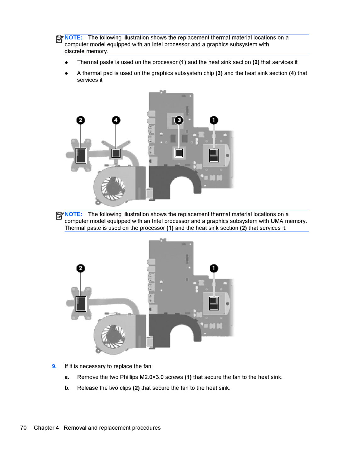
![]() NOTE: The following illustration shows the replacement thermal material locations on a computer model equipped with an Intel processor and a graphics subsystem with discrete memory.
NOTE: The following illustration shows the replacement thermal material locations on a computer model equipped with an Intel processor and a graphics subsystem with discrete memory.
●Thermal paste is used on the processor (1) and the heat sink section (2) that services it
●A thermal pad is used on the graphics subsystem chip (3) and the heat sink section (4) that services it
![]()
![]()
![]()
![]() NOTE: The following illustration shows the replacement thermal material locations on a computer model equipped with an Intel processor and a graphics subsystem with UMA memory. Thermal paste is used on the processor (1) and the heat sink section (2) that services it.
NOTE: The following illustration shows the replacement thermal material locations on a computer model equipped with an Intel processor and a graphics subsystem with UMA memory. Thermal paste is used on the processor (1) and the heat sink section (2) that services it.
9.If it is necessary to replace the fan:
a.Remove the two Phillips M2.0×3.0 screws (1) that secure the fan to the heat sink.
b.Release the two clips (2) that secure the fan to the heat sink.
70 Chapter 4 Removal and replacement procedures